1. Preparation Items
1.1. Install auxiliary tools
**Soldering Iron **: It is recommended to use a soldering iron with a power of 60W or higher and adjustable constant temperature (newcomers are advised to use a small tip).
**Solder wire **: It is recommended to choose lead-free solder wire with a thickness of 0.8~1mm and a purity of over 99% (lead-containing and lower tin content make soldering more difficult).
Tweezers: Used for wire picking and soldering (those with no heart of steel don't need them).
Flux: Used to turn difficult-to-solder materials into easy-to-solder ones.
PCB cleaner: Used to clean stains after soldering.
**Screwdriver **: It must be used to turn screws.
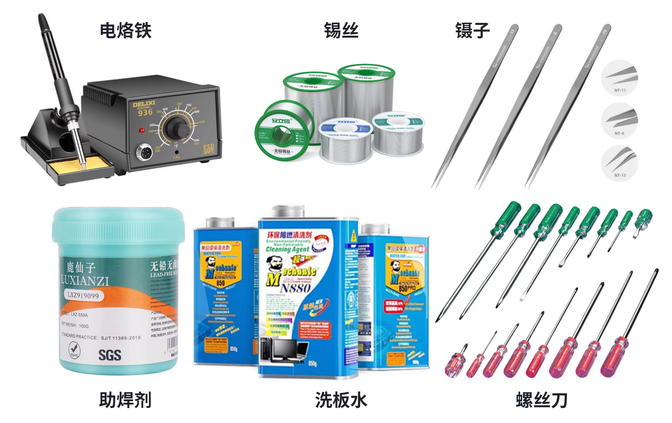 If you don't know how to choose among the above tools, it is recommended to purchase them all at "Weixiulao" or "Luxianzi" on Taobao.
UV glue and UV lamp: Used for fixing nuts and other places (only Ergo brand is recommended).
Multimeter: Used to measure batteries, check for short circuits, and check connections.
Computer or mobile phone: Used for debugging.
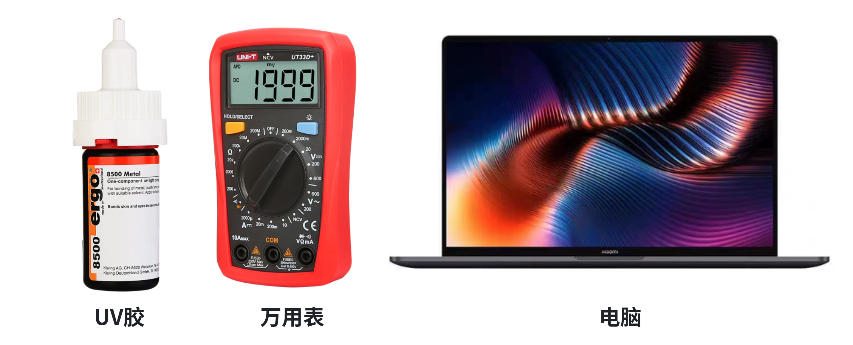 It would be best to have the above tools, but they are not mandatory.
1.2 Aircraft Minimum Flying System
**Flight Controller **: The flight control brain of an aircraft (it is recommended to choose the FY-FC-Pilot flight controller, which is suitable for beginners and integrates a receiver and data link).
ESC: One ESC drives one motor to rotate.
Frame: Used to secure components such as motors, electronic speed controllers, and flight controllers.
**Battery **: It's definitely used to supply power.
**Receiver **: Used to receive remote control commands.
Blade: Used to provide lift (i.e., for flying).
Remote Controller: It's for remote control (newbies are advised to download the DJI app and enter the simulated flight practice).
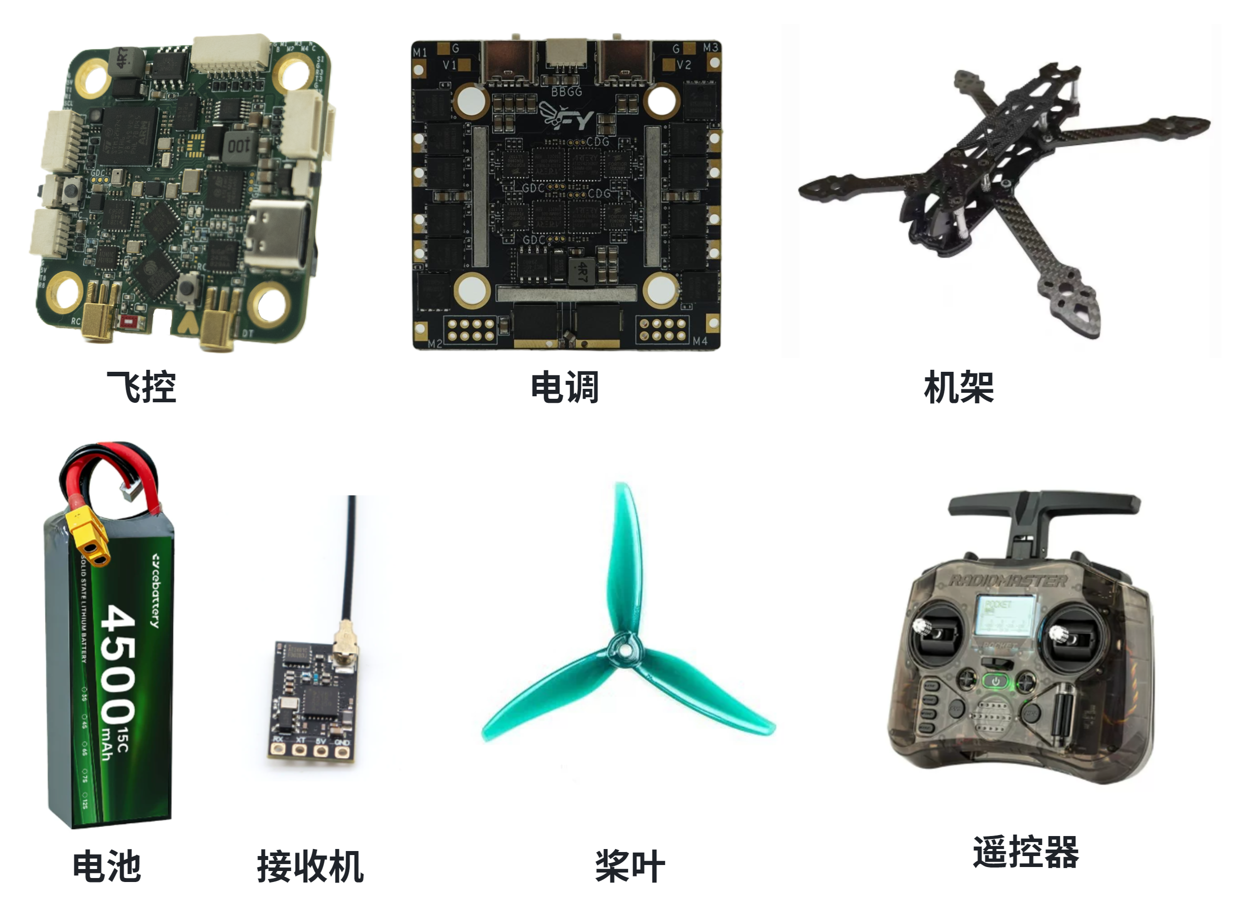 *The above components are essential for an aircraft to fly.
GPS and magnetic compass: Used for positioning and navigation, and it is also what enables the aircraft to hover stably outdoors. (GPS provides normal-precision positioning, while RTK provides ultra-high-precision positioning)
Optical flow and ToF: They are what enables an aircraft to hover stably indoors, used to measure displacement and altitude respectively. They cannot be used for navigation and positioning.
Data Transmission: Used for the mutual transmission of status information between the flight controller and the ground station. That is, it allows you to see the aircraft's status or transmit data between them without the need to connect the flight controller and the computer with a data cable.
Camera and image transmission: It allows you to see the first-person view of the aircraft from a long distance.
Onboard computer: Used to fuse various sensor data other than IMU and perform operations such as intelligent path planning. (Distinct from the flight controller, which controls the aircraft's attitude)
Pan-tilt: It allows the camera to rotate up, down, left, and right to view different directions while the aircraft remains stationary.
**Servo **: A rotary switch that can be used to control the opening and closing size. (This is used for bomb dropping)
Camera: Action camera - capable of recording first-person flight footage more clearly and without vibration. Binocular camera - used for image positioning and navigation.
LiDAR: It performs 360-degree, blind-spot-free scanning of the surrounding environment for real-time positioning and navigation.
**Airspeed indicator ** : Used only on fixed-wing aircraft.
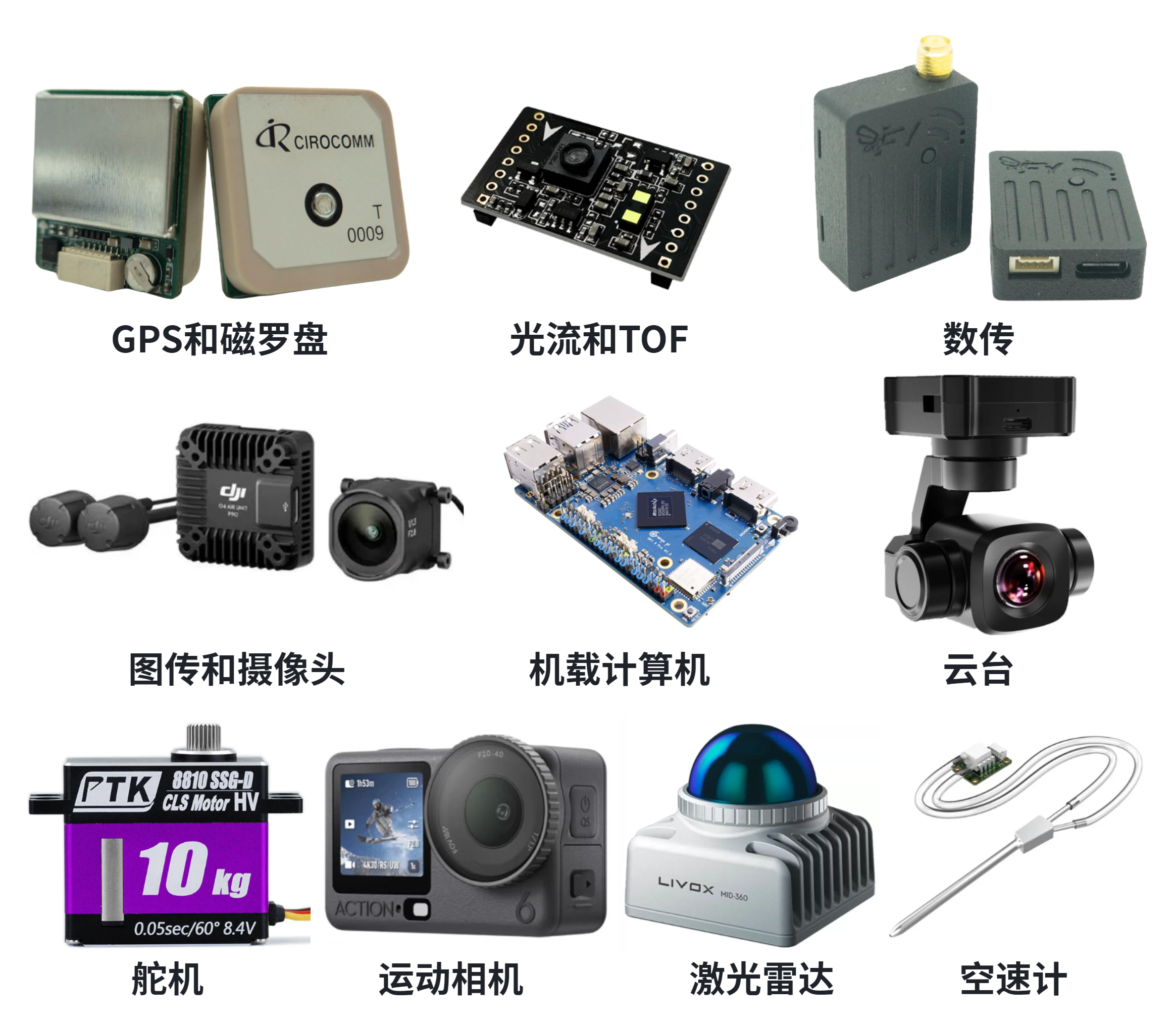 *The above components are used for auxiliary purposes. It is recommended to add GPS, magnetic compass, image transmission, and camera if conditions permit.
2. Drone Installation
2.1 Ensure that each component in the aircraft architecture is mutually compatible
Aircraft frame:** It must be rigid; otherwise, the aircraft will crash.** At the same time, ensure that there are appropriate screw holes to secure the motor, ESC, and flight controller, and that the propellers can rotate normally after all components are installed.
ESC and motor and battery: must be just right, **how many S motors are matched with how many S batteries and how many S ESC **(that is, the **voltage should be consistent **, S refers to the number of battery strings), otherwise either burn the motor or the motor cannot turn up. **How much power the motor is equipped with how much power ESC and how many C batteries **(that is, the **current should be consistent **, C refers to the discharge multiple of the battery), otherwise either the motor turns slowly or burns too fast.
Flight Controller: It must at least have two sensors, an IMU and a barometer, and can also output protocol signals supported by the electronic speed controller (ESC). Flight controllers and ESCs generally have three types of hole spacing: 20.5x20.5, 25.5x25.5, and 30.5x30.5, with different spacings suitable for different sizes of frames.
Blades and motors: It is essential to first assess the total weight of the aircraft and check whether the force efficiency table of the motor combined with the blades meets the requirements. If it is too heavy, it won't be able to fly. (Mainly, for frames smaller than 3 inches, weight needs to be considered, while large aircraft can be handled casually)
2.2 Installation Key Points
Blades must be installed last, blades must be installed last, blades must be installed last. (For the sake of your own hands!)
Each rack installation step is different, and you can assemble it according to the instructions of the purchased rack. ** The most important thing is to first figure out how all the wires should be routed. **
If possible, solder the large capacitor, which can make the aircraft fly more stably and reduce the probability of ESC burnout. Reversing the soldering of the large capacitor will cause it to burn out, so ensure that the long lead of the large capacitor is soldered to the positive pole and the short lead to the negative pole. At the same time, try to keep the soldering of the large capacitor's leads as short as possible; if they are too long, it will be equivalent to having no capacitor at all.
**The flight controller must be firmly fixed, ensuring that it cannot move even a tiny bit, even when shock absorbers are installed. If the aircraft experiences vertical jolts during flight, the shock absorbers can be removed and the flight controller directly locked. **
Directional modules (such as flight controllers, magnetic compasses, etc.) must be installed in the specified direction; otherwise, it will cause the aircraft's directional control to malfunction.
The overall center of gravity of the aircraft must be centered to maintain a stable flight attitude, and it is best if the flight control can also be centered.
All motor wire welding can be done in sequence, and now flight controllers and electronic speed controllers basically support commutation via the host computer.
All antennas on the aircraft should be placed as far apart from each other as possible and located in the most exposed parts of the aircraft to maintain optimal wireless transmission performance.
For items such as batteries and action cameras that need to be secured with magic tape, it is recommended to attach non-slip pads to their bottoms, which can better secure them.
Be sure to check the wiring definitions between components to ensure no wiring errors.
3. System Debugging (PX4)
The following operations are all based on the FY-FC-Pilot flight controller operation demonstration. If you don't know how to operate, ask Doubao or go directly to the PX4 official website https://docs.px4.io/main/zh/ to check.
3.1, PX4 Flashing Program
All flight controllers come pre-flashed with firmware and can be used directly. Unless you want to replace the firmware version or design application layer programs, there is no need to re-flash.
All relevant software installation packages and firmware can be downloaded via Baidu Netdisk.
Compile Firmware:
For those who are unfamiliar with the operation (having never touched the Linux system and unable to access the Internet scientifically), simply use the firmware provided by the merchant, which are the bootloader file: hkust_nxt-dual_bootloader_V1-16-1.bin and the application file: hkust_nxt-dual_default_V1-16-1.px4 respectively.
If the environment system has already been configured according to the official requirements of PX4, then navigate to the project directory, enter the following command to compile, and finally check the files generated by the compilation in the Build folder (it is recommended to compile only the stable version of the firmware).
make hkust_nxt-dual_bootloadermake hkust_nxt-dual_default- Use the STM32CubeProgrammer software to burn the bootloader file (which can be understood as the computer's BIOS).
Press and hold the BOOT button on the flight controller, then connect the flight controller to the computer via a Type-C cable for power-on communication. Release the button after powering on.
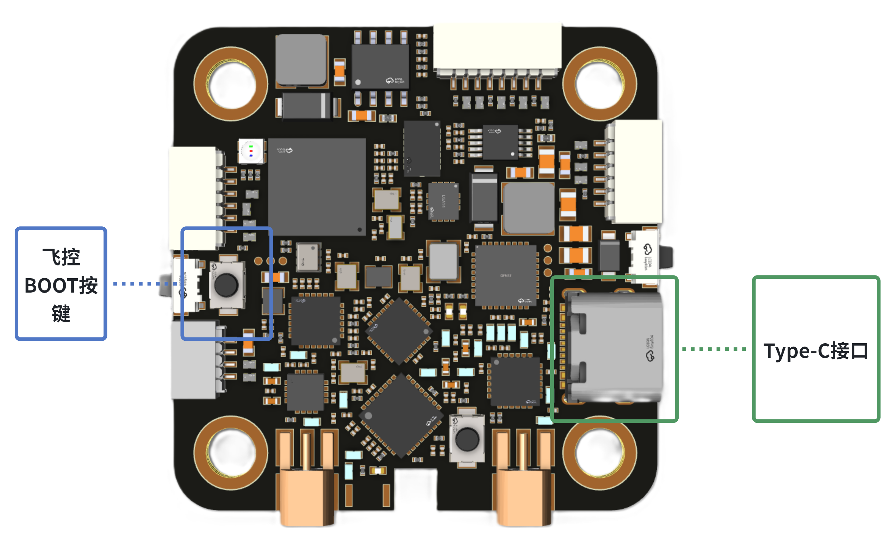
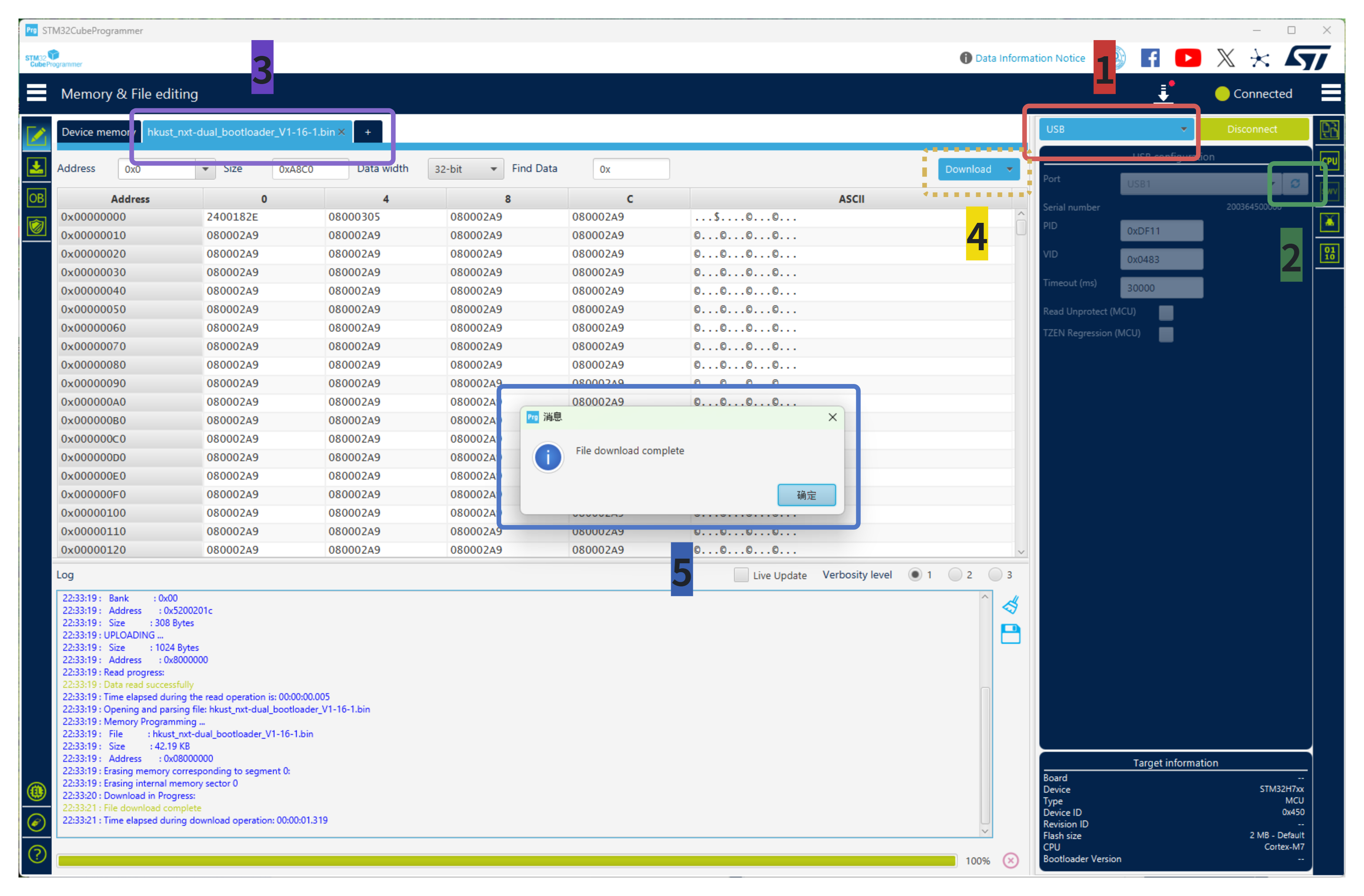
Open the STM32CubeProgrammer software and follow the steps in sequence:
Click on the connection method in the upper right corner of the software and select USB.
Click the refresh symbol, then refresh to display USB1. If there is no change after refreshing, power off and then press and hold the BOOT key while powering on again.
Click "openfile" to open the bootloader file.
Finally, click "Download" and wait for the programming to complete.
A pop-up window displaying "File download complete" indicates successful programming (similarly, the indicator light on the flight controller flashing green after power cycling also indicates successful programming).
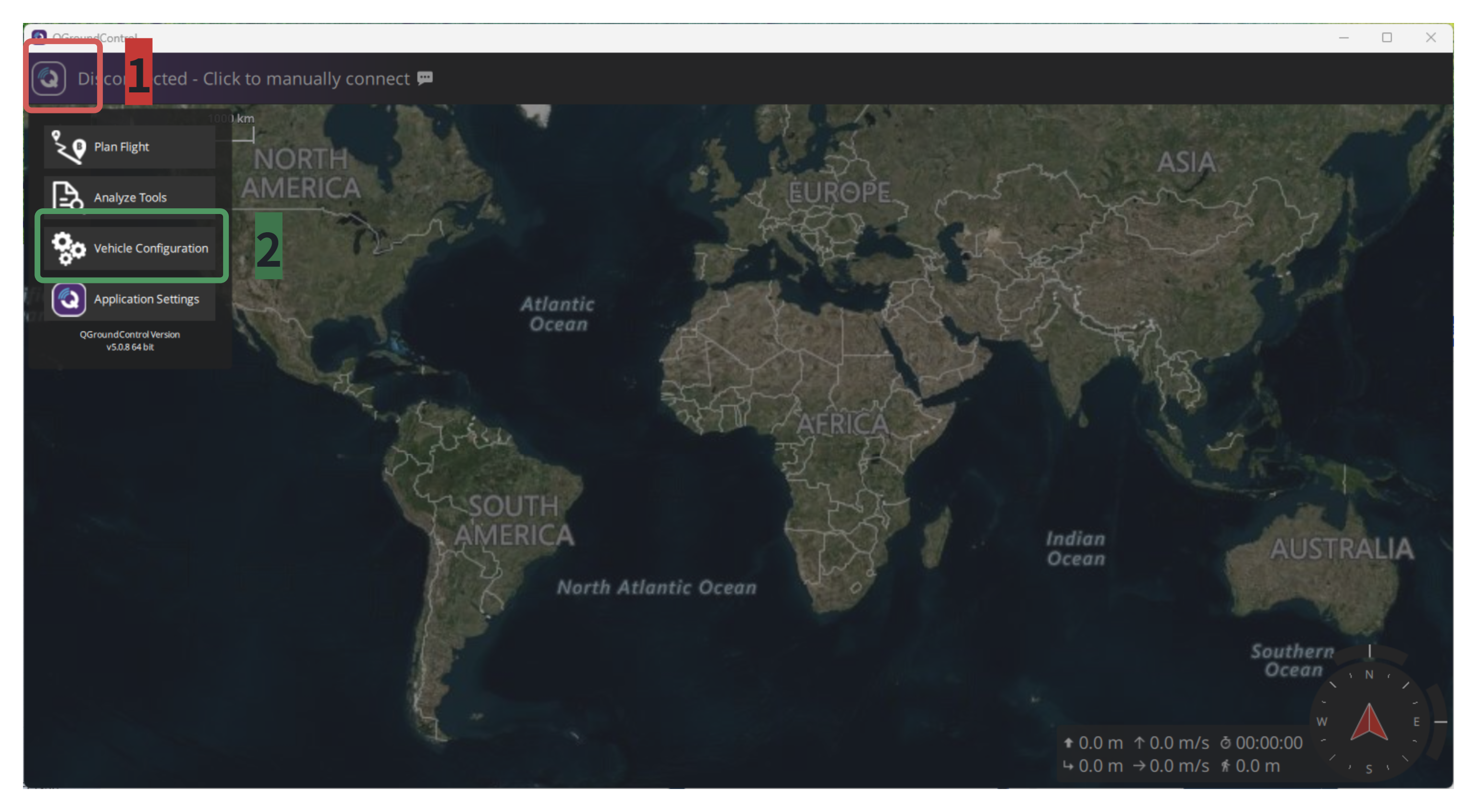
 5. After burning the bootloader file, power off the flight controller, then open the QGroundControl software and follow the steps in order:
Click the icon in the top-left corner of the QGroundControl software, then select "Vehicle Configuration" to enter the configuration menu.
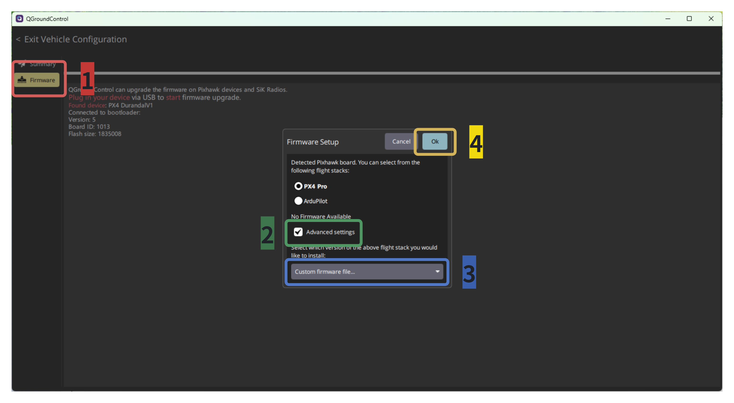
Click the "Firmware" button, then power on the flight controller by connecting it to the computer via Type-C (do not hold the BOOT button while powering on, otherwise the application layer file cannot be flashed). After the computer recognizes the flight controller, it will automatically pop up a prompt to download (if the pop-up does not appear, check whether the bootloader file has been successfully flashed).
Click the "Advanced settings" button, then select "Custom firmware file...", and finally click the "OK" button. Select the application layer file (in.PX4 format), and the software will automatically flash it.
3.2. PX4 System Debugging
Sensor calibration should be performed only after the aircraft is fully assembled; otherwise, the aircraft will be too fragmented, and sensor inaccuracies may still occur even after calibration. All the following steps are based on the debugging after the aircraft is fully assembled, and can be configured in sequence.
Open the QGroundControl software, enter "Vehicle Configuration" to configure the aircraft.
3.2.1, "Summary" Interface:
Displays the current general status of the aircraft. The aircraft can only be unlocked for takeoff when all configurations are green or there are no red ones (red indicates no configuration or configuration error). 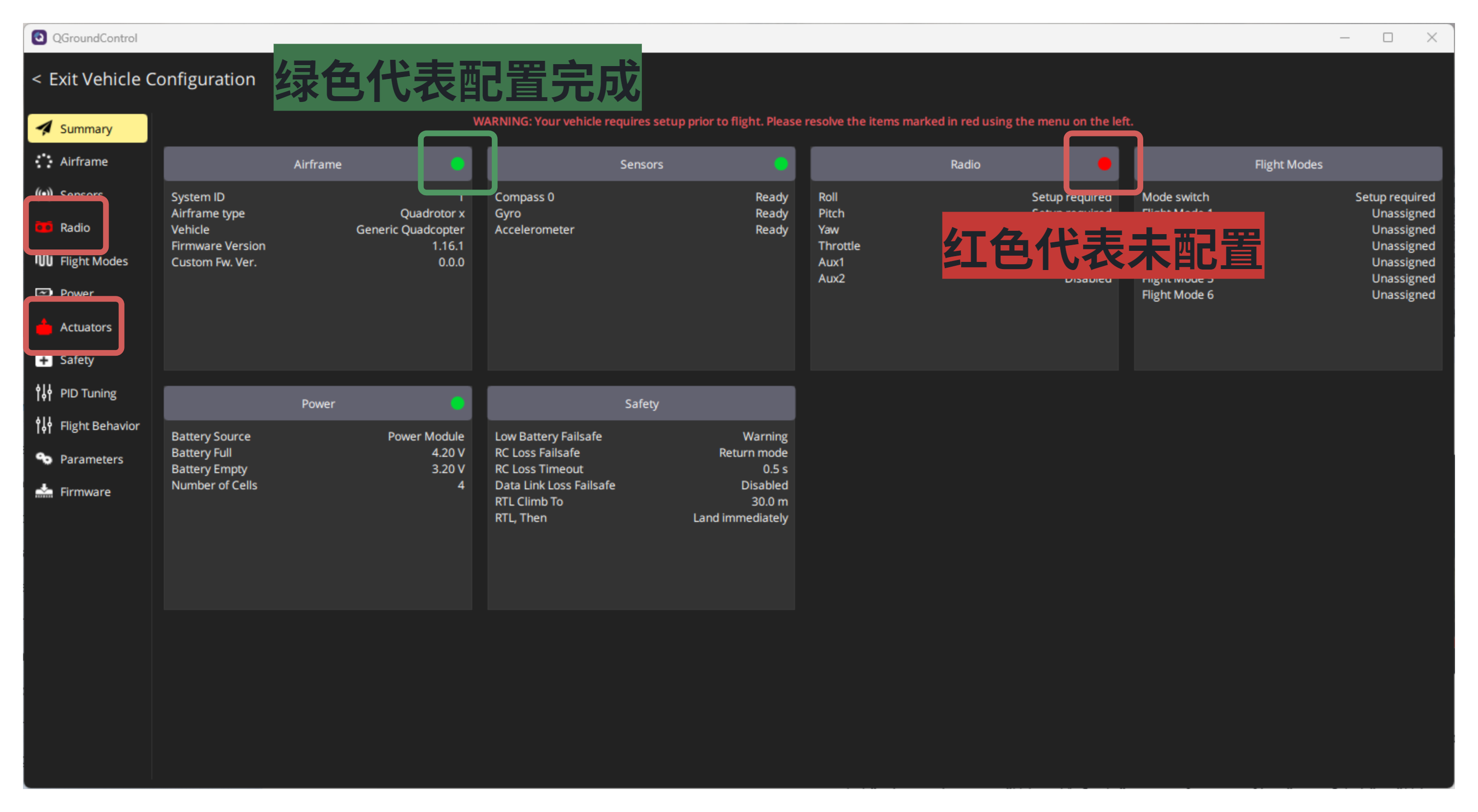
3.2.2, "Airframe" Interface:
Select the aircraft model ( ** must be selected according to the actual model and cannot be left unselected ** ). 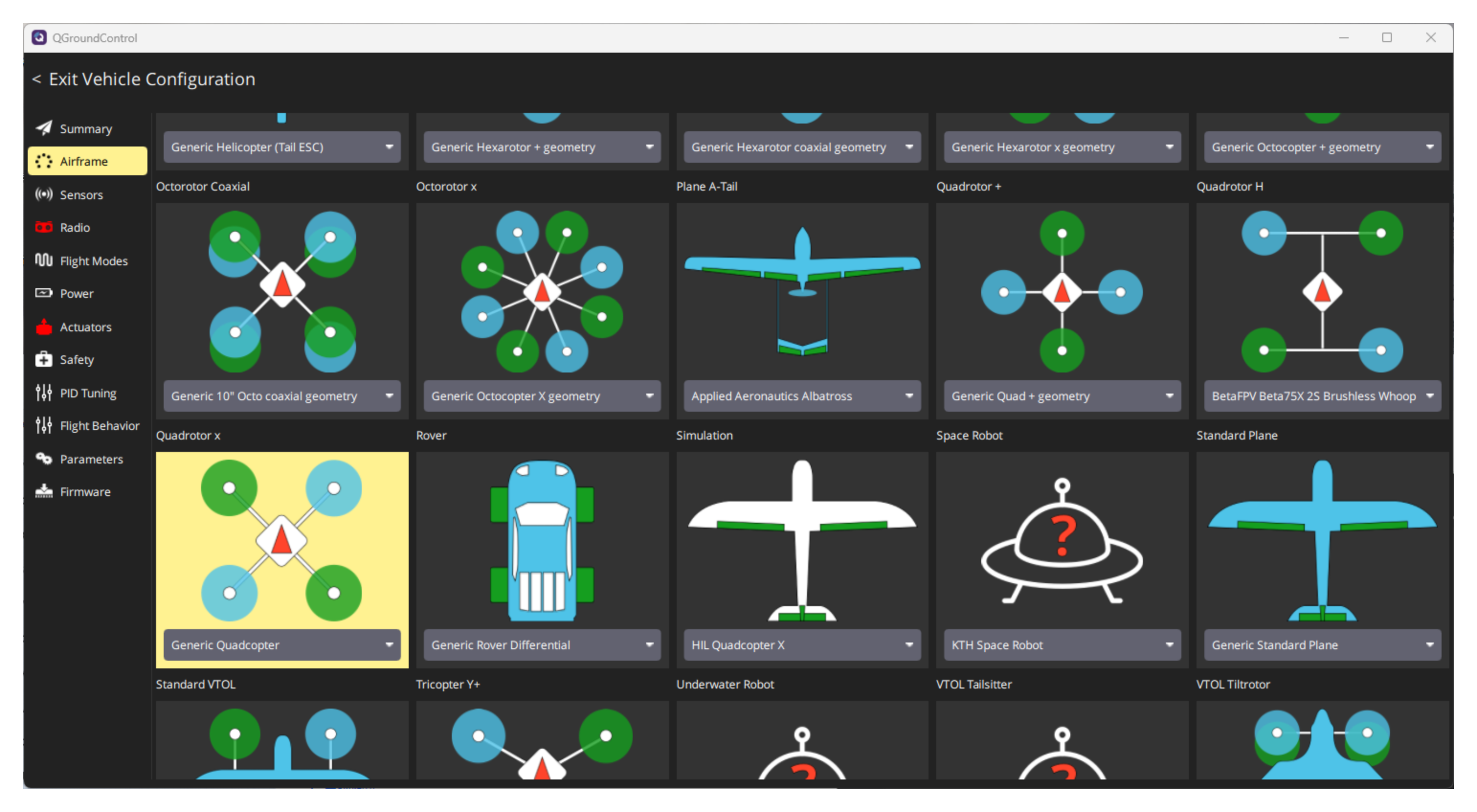
3.2.3, "Sensors" Interface:
It is used to calibrate sensors and determine the forward direction of the aircraft. Only the three sensors "Compass", "Gyroscope", and "Accelerometer" need to be calibrated. When there is no external magnetic compass, the "Compass" sensor does not need to be calibrated.
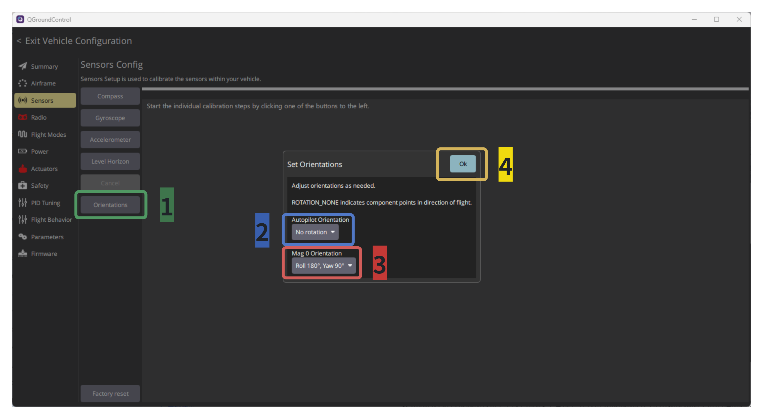
- First, associate the sensor direction with the aircraft's forward direction; otherwise, the direction will be confused when controlling the remote-controlled aircraft. Additionally, once the calibration is set up, there is no need to repeatedly select the direction settings. The orientation of the flight controller and magnetic compass is provided by the manufacturer. Taking the FY-FC-Pilot flight controller and FY-FC-M10 magnetic compass as an example: select "No rotation" for "Autopilot Orientation" (the forward direction of the aircraft is coordinated with the direction of the IMU), and select "Roll 180°, Yaw 90°" for "Mag 0 Orientation" (the forward direction of the aircraft is coordinated with the direction of the magnetic compass). ** After becoming familiar with the operation, the orientation selection can be adjusted according to the actual installation of the flight controller and magnetic compass. When performing sensor calibration, pay attention to check whether the indicated directions of the aircraft are consistent with those indicated by the QGroundControl software. If they are inconsistent, you need to exit the calibration and reset the correct directions. **
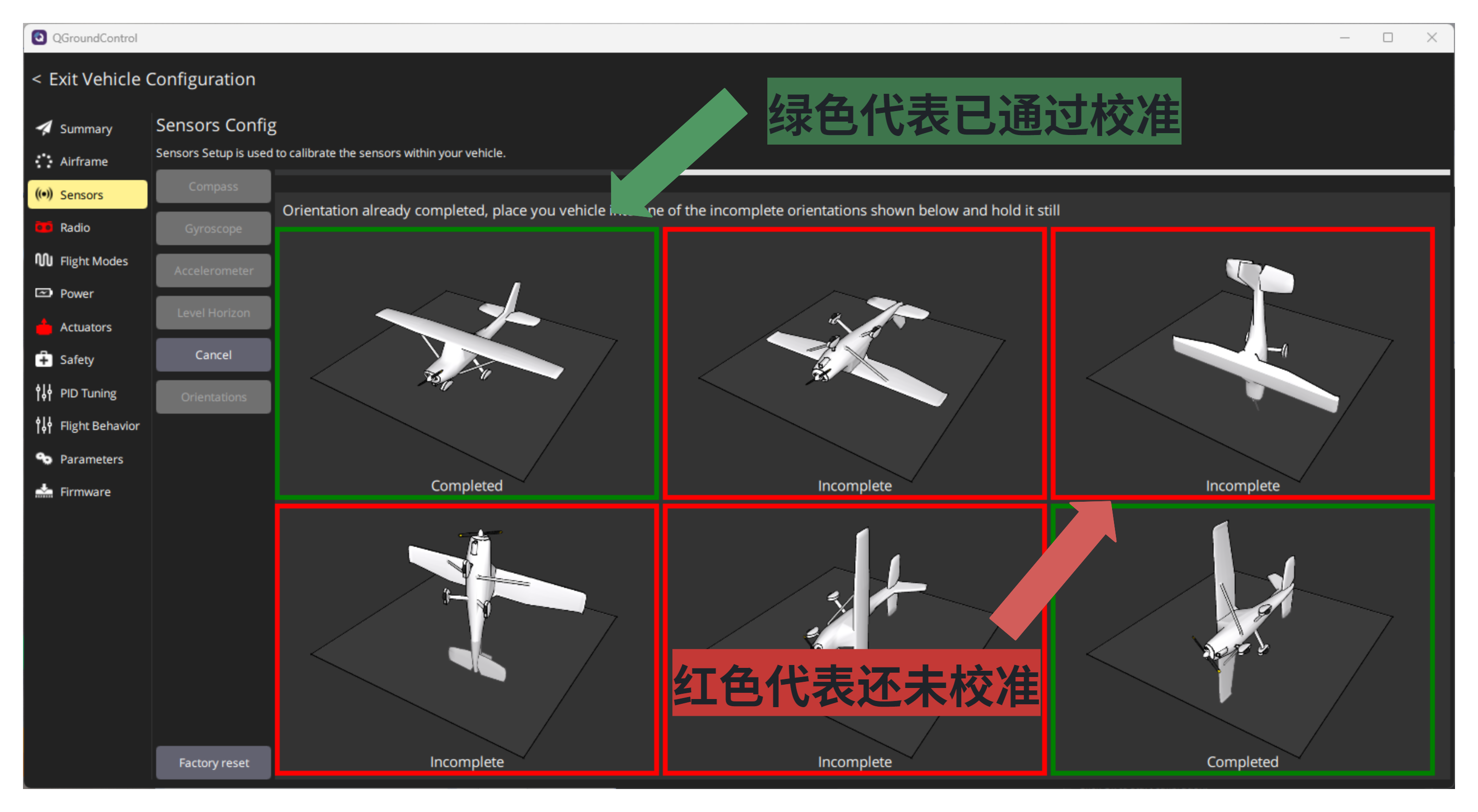
- Calibration of the "Compass" magnetic compass sensor: Select the forward direction of the aircraft, and perform 6-sided rotation calibration according to the operation (make sure to secure the flight controller and magnetic compass firmly; only simultaneous rotation counts as successful calibration. Even if the calibration passes without simultaneous rotation, the performance will still deviate significantly). When the frames of all 6 sides turn green, it indicates successful calibration.
"Gyroscope" Gyroscope Sensor Calibration: Make sure to place the aircraft horizontally and facing upward.
Calibration of the "Acclerometer" accelerometer sensor: The difference from the calibration of the "Compass" magnetic compass sensor is that it can be calibrated without rotation.
**"Power" Interface **: Used to set battery voltage and current parameters (fill in the parameters according to actual conditions). Voltage is generally measured by the flight controller, and current is generally measured by the electronic speed controller.
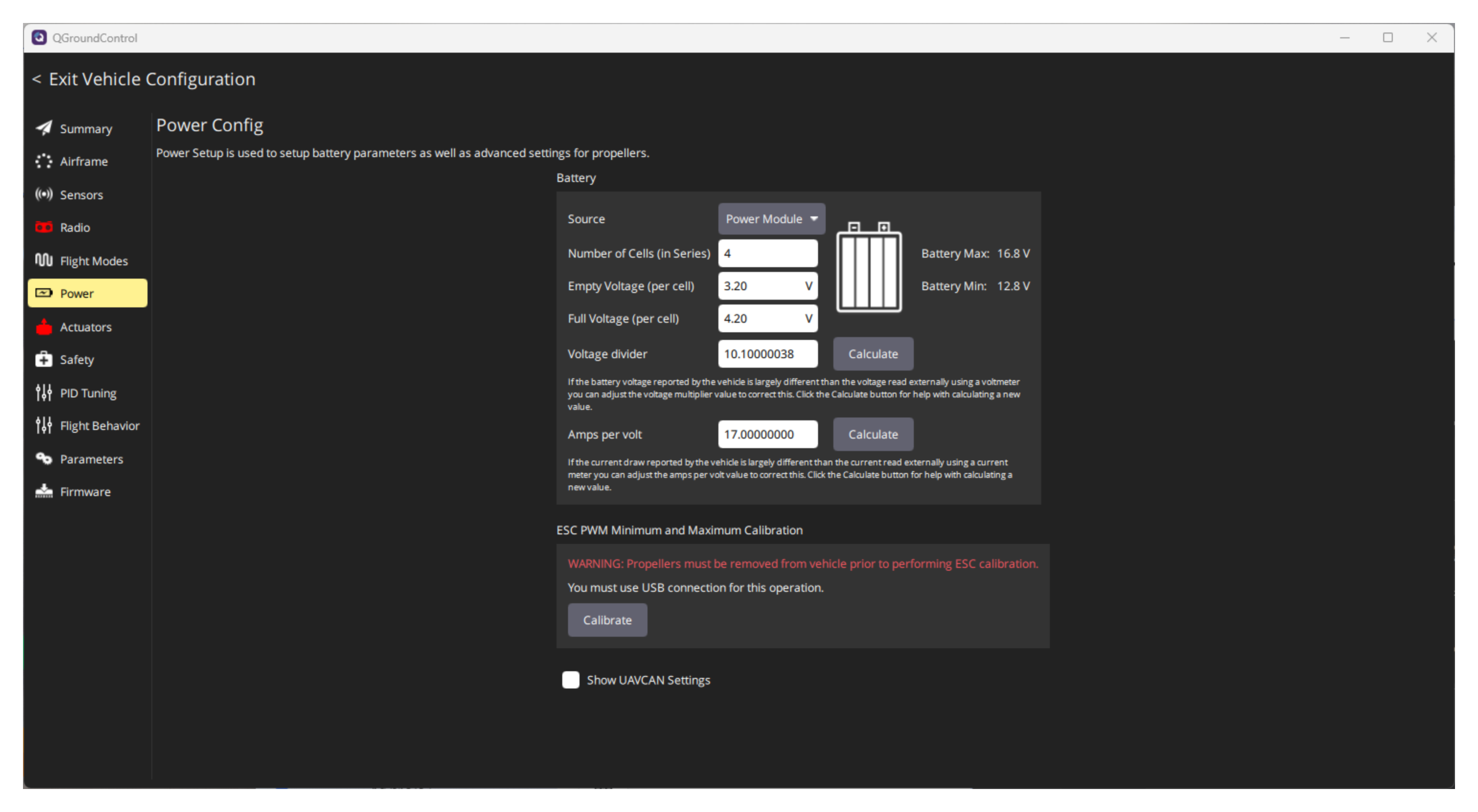
"Number of Cells (in Series)" Battery String Count: refers to how many S batteries there are.
"Empty Voltage (per cell) " The empty voltage of each battery: is the voltage of a single battery when it is **dead **(don't ask why it is not 0V when it is dead, ask Doubao), and it needs to be set according to the parameters marked by the battery.
"Full Voltage (per cell)" refers to the voltage of a single cell when it is ** fully charged **, which needs to be set according to the parameters marked on the battery.
Voltage ratio of the "Voltage divider" battery: ** must be accurate, used for real-time calculation of the battery voltage value. ** This value can be directly provided by the manufacturer or calculated through measurement. The ratio of the FY-FC-Pilot flight controller is 11. If you have a multimeter, you can measure the actual voltage value of the battery and then calculate the ratio through automatic calculation. Click the "Calculate" button on the right side of "Voltage divider", then enter the measured voltage value, and finally click the "Calculate" button again to automatically generate the ratio value.
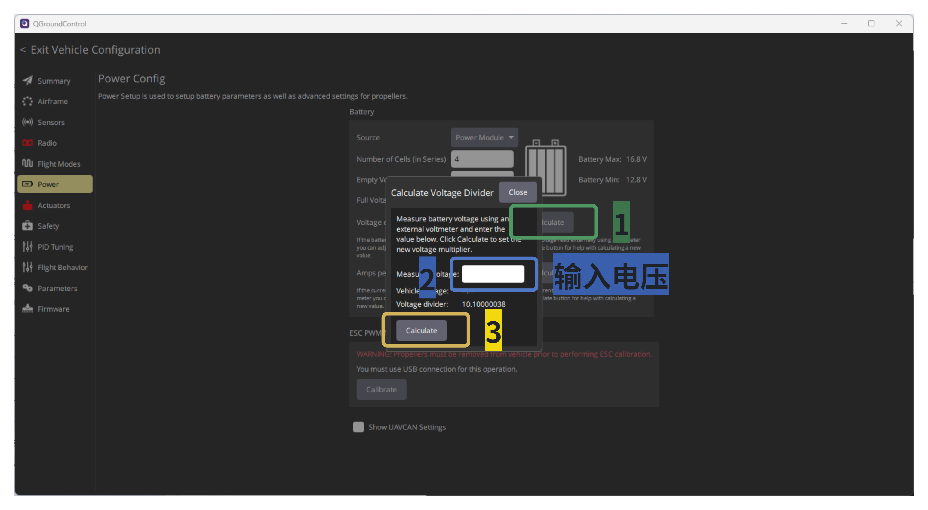
The current ratio of the “Amps per volt” battery: It can be left unset as it has little impact. However, it needs to be set for those who need to know the battery's power level.
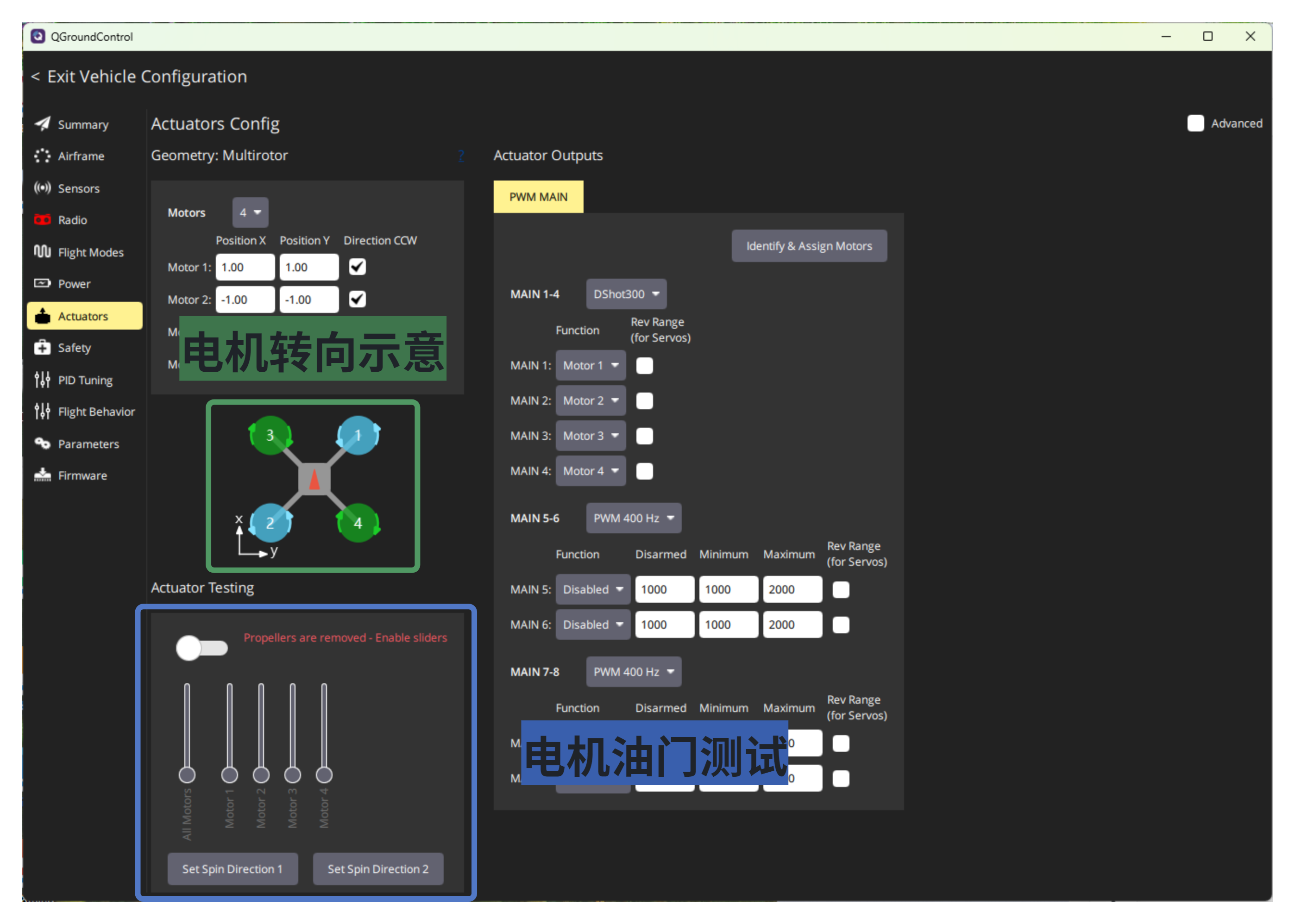
**"Actuators" Interface **: Used to set motor-related parameters ( ** be sure to unload the propellers before performing this configuration ** ).
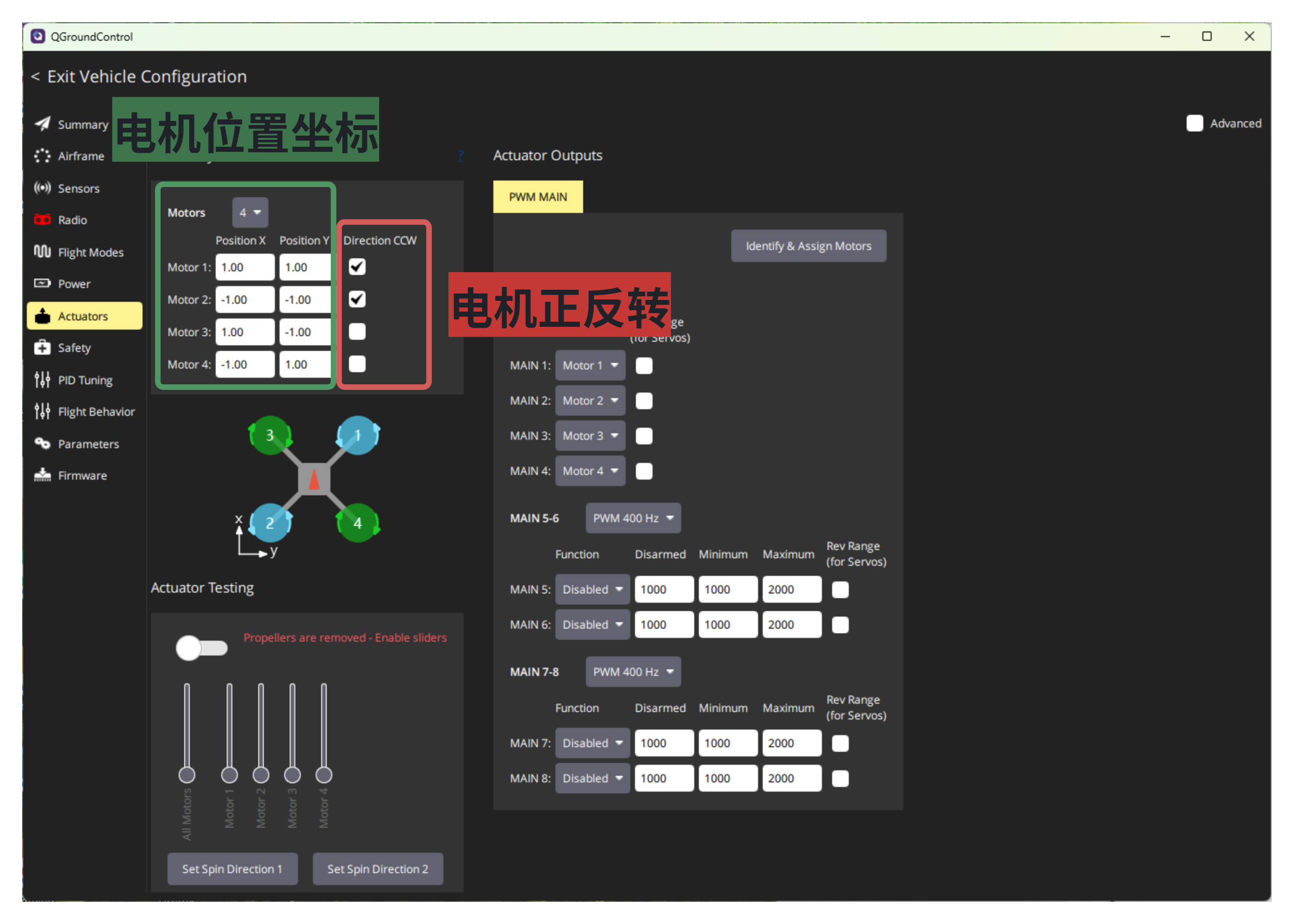
- Set the position coordinates and rotation direction of the motors: The position coordinates of the motors are determined by the frame, and thisparameter should be as accurate as possible, as it will affect the stability of the aircraft (unit: meters). The "Direction CCW" column is used to set the rotation direction of the motors, with a checkmark indicating reverse rotation.
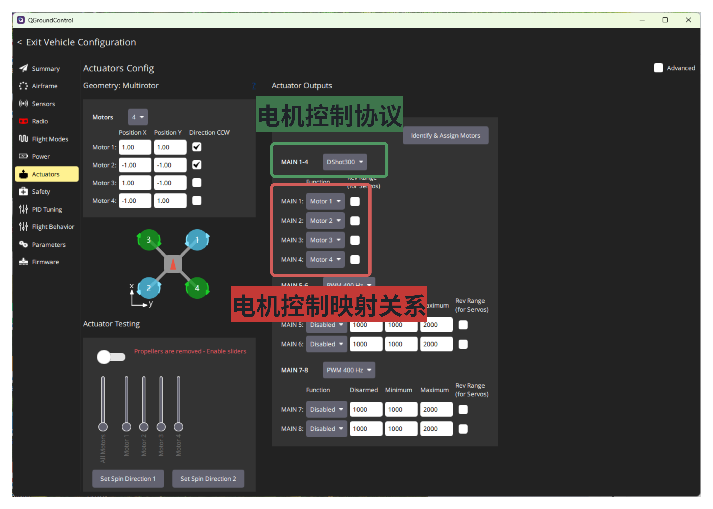
- Set the control protocol and mapping relationship of the motors: It is recommended to use the Dshot300 motor control protocol, which can optimally meet the requirements of most electronic speed controllers. Then map the motor controls according to the control pins of the flight controller.
- Motor debugging: Manually start each motor one by one (during testing, it is recommended to give a little throttle), then debug** the motor's rotation direction to ensure it is consistent with the requirements shown in the diagram; inconsistency will cause the aircraft to fail to take off or crash immediately after takeoff**.
3.2.4, "Safety" Interface:
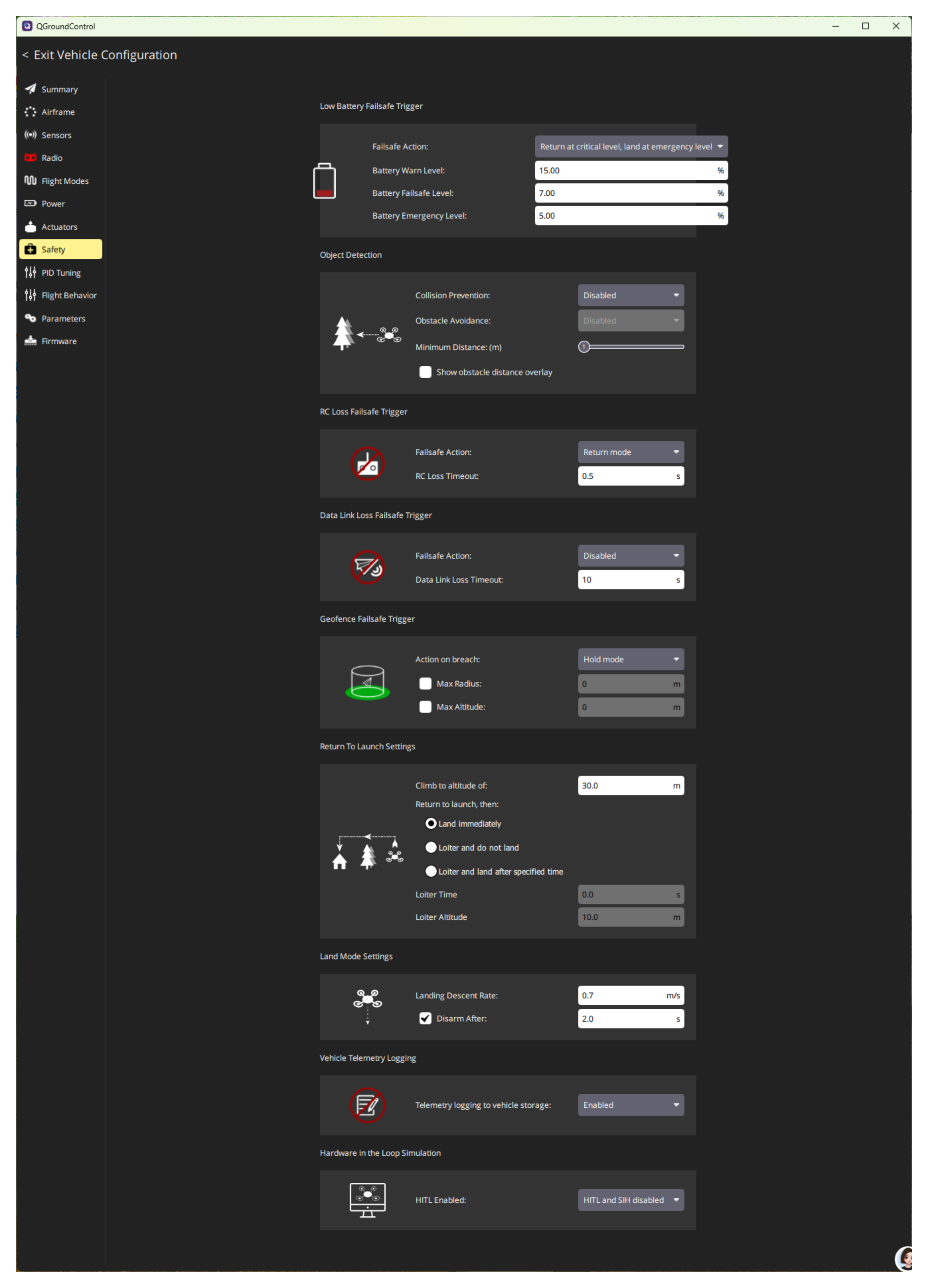
Used to set various accidental trigger conditions for emergency hazard avoidance operations (requires the aircraft to be equipped with GPS and magnetic compass modules to ensure normal hazard avoidance operations)
- "Low Battery Failsafe Trigger": Used to set the battery level threshold below which "alarm", "land", or "return to home automatically" operations will be triggered. It is recommended to set the following modes:
Select the "Return at critical level, land at emergency level" mode: return at critical voltage and land at emergency voltage.
Set the "Battery Warn Level" battery alarm voltage to 25, and QGC will automatically alarm when the battery level is below 25%.
The "Battery Failsafe Level" is set to 20, and the aircraft will automatically return when the battery level drops below 20%.
The "Battery Emergency Level" battery emergency voltage is set to 50, and the aircraft will automatically land when the battery level is below 5%.
"Object Detection" Obstacle Detection: Used with sensors such as TOF, it is recommended to default to "Disable".
"RC Loss Failsafe Trigger": Set "Failsafe Action" to "Return mode", and set "RC Loss Timeout" to 1s.
"Data Link Loss Failsafe Trigger": Set "Failsafe Action" to "Return mode", and set "Data Link Loss Timeout" to 10 seconds.
"Geofence Failsafe Trigger" Geo Fencing Trigger: Used to set the flight range of the aircraft. Not checking it means there is no range limit. Set "Action on breach" to "Return mode", "Max Radius" to 2000, and "Max Altitude" to 150.
"Return To Launch Settings": Set "Climb to altitude of" to 30, and select "Land immediately".
"Land Mode Settings": Set the "Landing Descent Rate" to 1, and do not check the "Disarm After" option for automatic disarming after landing.
Logging for "Vehicle Telemetry Logging": Select "Enable" (logging and saving of logs will only occur when a TF card is inserted).
3.2.5, "Parameters" Interface:
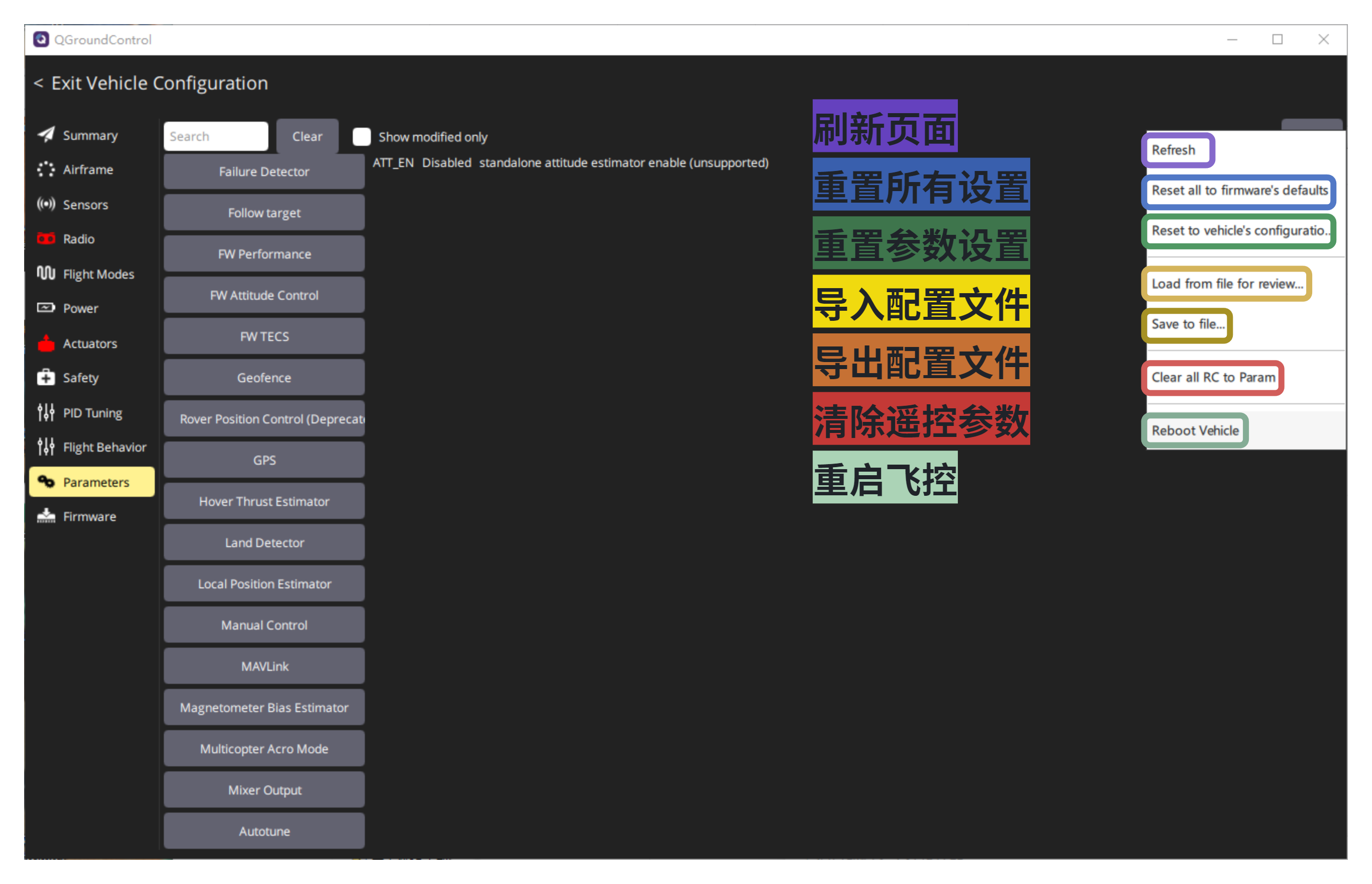
It is used to configure flight control peripherals and internal related parameters, meaning that all configurations of the aircraft can be directly operated through parameterization. This interface mainly consists of a "Search" bar, a "Module" bar, a "Parameter Name" bar, a "Parameter" bar, and a "Parameter Introduction" bar. Relevant parameters can be found through the "Module" or "Search". 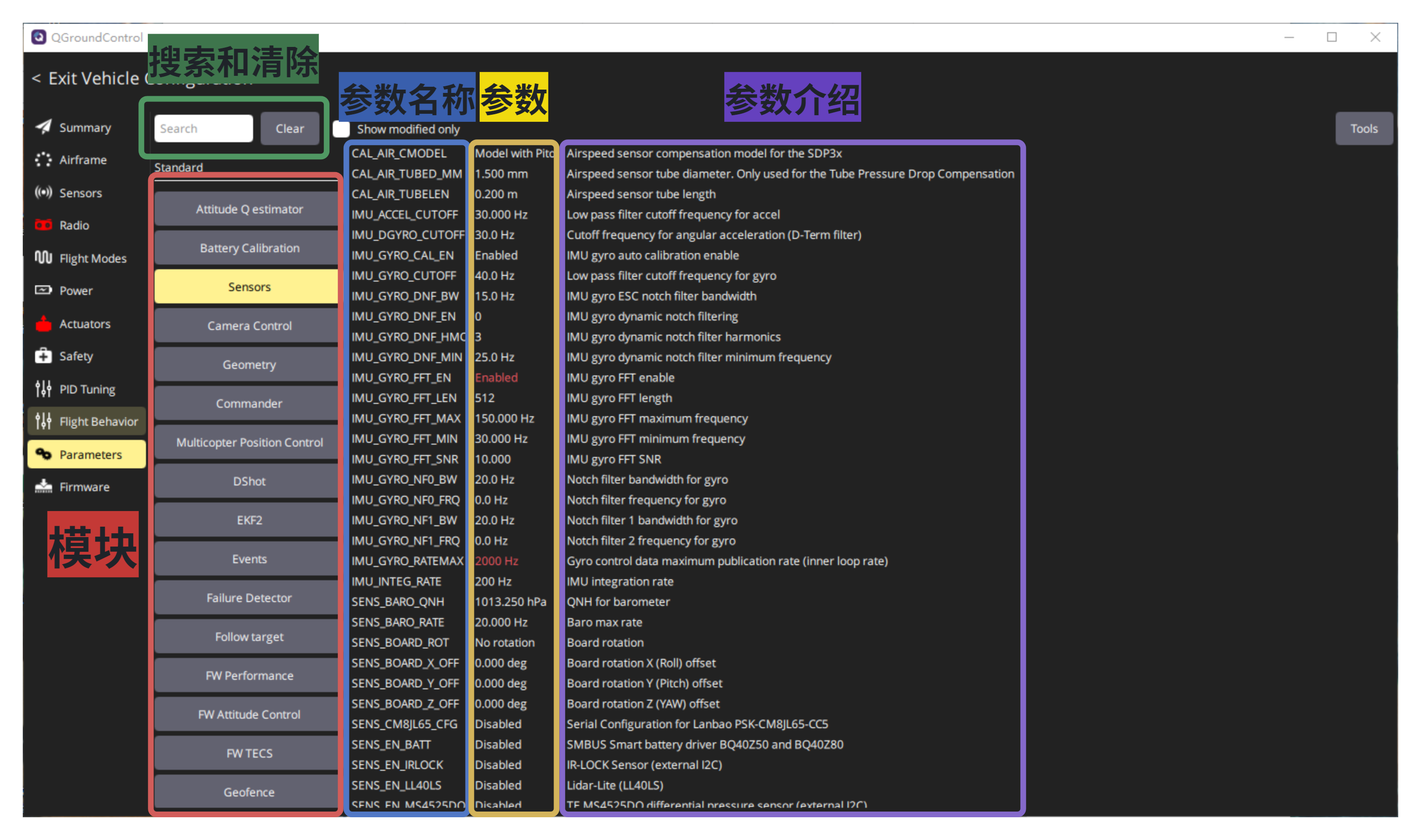 Relevant operations can be performed through the "Tools" in the upper right corner of the "Parameters" interface. ** If you need to change the interface (for example, change the serial port of GPS to the serial port function of data transmission), you must first modify the interface parameters and then restart the flight controller before proceeding with the next configuration. **
  The mapping relationships between all serial ports of FY-FC-Pilot flight controller and PX4 are as follows (if you don't know what a serial port is, just ask Doubao):
| PX4 | |
|---|---|
| UART1 | GPS1 |
| UART2 | TELEM1 (already used as a remote control receiver) |
| UART3 | GPS2 |
| UART4 | TELEM2 (already used for data transmission) |
| UART5 | Radio controller (only supports SBUS) |
| UART6 | Debug Interface, Terminal Communication |
| UART7 | TELEM3 |
| UART8 | TELEM4 |
1. Speed Setting:
"MPC_XY_VEL_MAX": Maximum velocity setting in the horizontal direction.
"MPC_Z_VEL_MAX_UP": Maximum upward velocity setting in the vertical direction.
"MPC_Z_VEL_MAX_DN": Maximum descent velocity setting in the vertical direction.
"MPC_ACC_HOR_MAX": Maximum acceleration setting in the horizontal direction.
"MPC_JERK_MAX": Maximum jerk setting for vertical and horizontal directions in vertex mode (the smaller the jerk, the smoother the aircraft accelerates).
"MPC_VEL_MANUAL": Maximum horizontal speed setting in fixed-point mode.
"MPC_TILTMAX_AIR": Maximum flight tilt angle of the aircraft in the air (the larger the angle, the faster the flight speed can be).
"MPC_TILTMAX_LND": Maximum flight tilt angle of the aircraft during landing (the smaller the angle, the smoother the landing).
2. Remote Control Settings:
"RC_PORT_CONFIG": Sets the serial port corresponding to the remote control receiver. If using the ELRS receiver on the FY-FC-Pilot flight control board, select "TELEM1"; if using an external SBUS receiver, select "Radio controller" (SBUS receivers can only be connected to interfaces with SBUS functionality), and only one of them can be selected as the remote control receiver.
Restart the flight controller (you can restart it without powering off through the "Reboot Vehicle" function in the "Tools" tool).
设置串口的波特率:使用FY-FC-Pilot飞控板载的ELRS,就将"SER_TEL1_BAUD"参数手动输入”420000“。使用外部的SBUS接收机,无需更改。
”RC_INPUT_PROTO“:设置接收的通讯协议。使用FY-FC-Pilot飞控板载的ELRS,就选择"CRSF"。使用外部的SBUS接收机,就选择"SBUS"。
三、数传设置(使用MAVLlink协议):
"MAV_0_CONFIG":设置MAVLink0数传对应的串口。使用FY-FC-Pilot飞控板载的数传就选择”TELEM2“。由于数传发送接收的是MAVLink0接口数据,因此可以同时最多设置3个串口来通讯数据,另外配置"MAV_1_CONFIG"和"MAV_2_CONFIG"接口即可,但是只有MAVLink0接口可以配置其它相关参数。
重启飞控(通过”Tools“工具中的”Reboot Vehicle“功能即可不用断电重启)。
设置串口的波特率:使用FY-FC-Pilot飞控板载的数传,就将"SER_TEL2_BAUD"参数选择”57600 8N1“。
"MAV_0_MODE":设置MAVLink0接口数据传输的模式。选择”Normal“模式(所有数据都能互传),也可以根据实际选择其它模式。
"MAV_0_FORWARD":用于MAVLink0接口的数据是否转发到MAVLink1和MAVLink2接口。当只用到一个接口时候,选择”Disable“。当外接如机载计算机等外设时选择”Enable“。
"MAV_0_RATE":设置MAVLink0接口数据传输的最大数率。速率越大,越容易数据丢包和通讯不上,但是响应速度越快。因此建议设置范围为600~1200B/S即可。
四、GPS设置:
普通精度的只建议选用UBLOX品牌的产品(PX4高度兼容UBLOX的产品),高精度的RTK随便品牌都可以。
"GPS_1_CONFIG"**:**设置GPS1(主GPS接口)对应的串口,选择”GPS1“。
"GPS_1_GNSS"**:**选择支持的定位系统,根据GPS模块来选择(可以直接全选)。
"GPS_1_PROTOCOL"**:**设置GPS1的通讯协议。选用UBLOX品牌的产品就选择“u-blox”,其它的根据GPS模块来选择。
"SER_GPS1_BAUD":设置GPS1接口的波特率。选择"Auto"即可。
五、磁罗盘设置:
只能选用QMC5883/IST8310/RM3100等PX4支持的磁罗盘,否则接其它磁罗盘会没有任何反应。
“SYS_HAS_MAG”**:**设置磁罗盘的数量,有多少个磁罗盘就填多少(通常没有任何干扰只要一个即可)。
“EKF2_MAG_TYPE”**:**磁罗盘融合模式选择,选择“Automatic”即可(开启更精准)。
六、气压计设置:
“SENS_EN_SPA06”**:**开启FY-FC-Pilot飞控板载的SPA06气压计,选择"Enable"。
“EKF2_BARO_CTRL”**:**气压计融合选择,选择"Enable"。
“EKF2_HGT_REF”**:**高度参考融合选择,可根据选择"GPS"或者“Barometric pressure”。
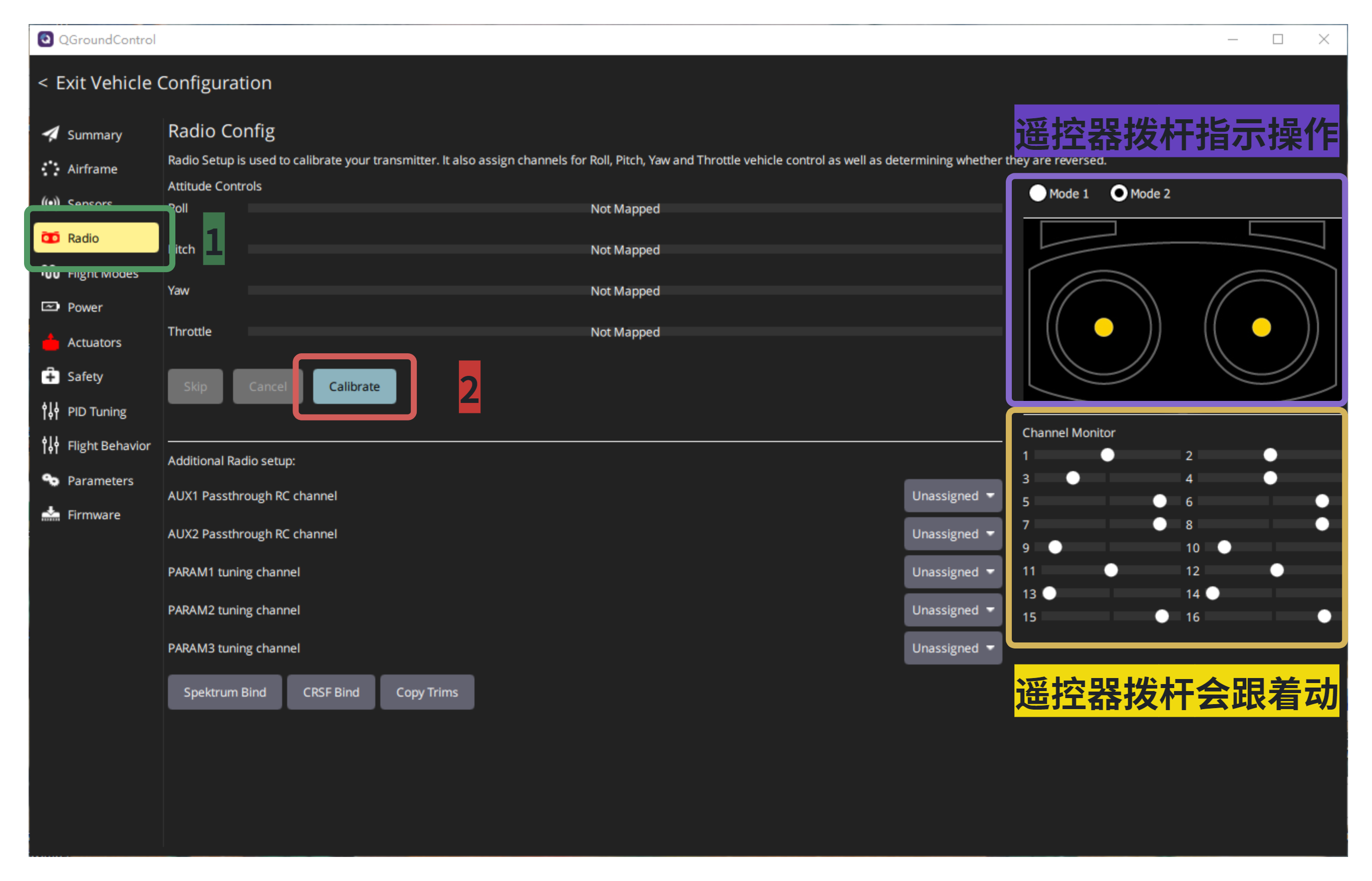
“Radio"界面:当配置完遥控设置后,将遥控器和接收机对频连上,然后进行遥控器校准。(当拨动遥感时,QGC对应的信道有变化即说明遥控器能够控制飞机),然后跟着遥控指示操作进行拨杆来校准。
3.2.6、“Flight Modes"界面:
在校准完遥控器后,根据遥控器的挡位和拨杆来进行飞行模式设置(以FY-FC-Pilot飞控板载的ELRS接收机和RadioMaster遥控器为参考)。当选择完通道后,可以通过按键开关来切换模式,当模式字体变成黄色时,说明在当前的按键开关挡位下模式生效。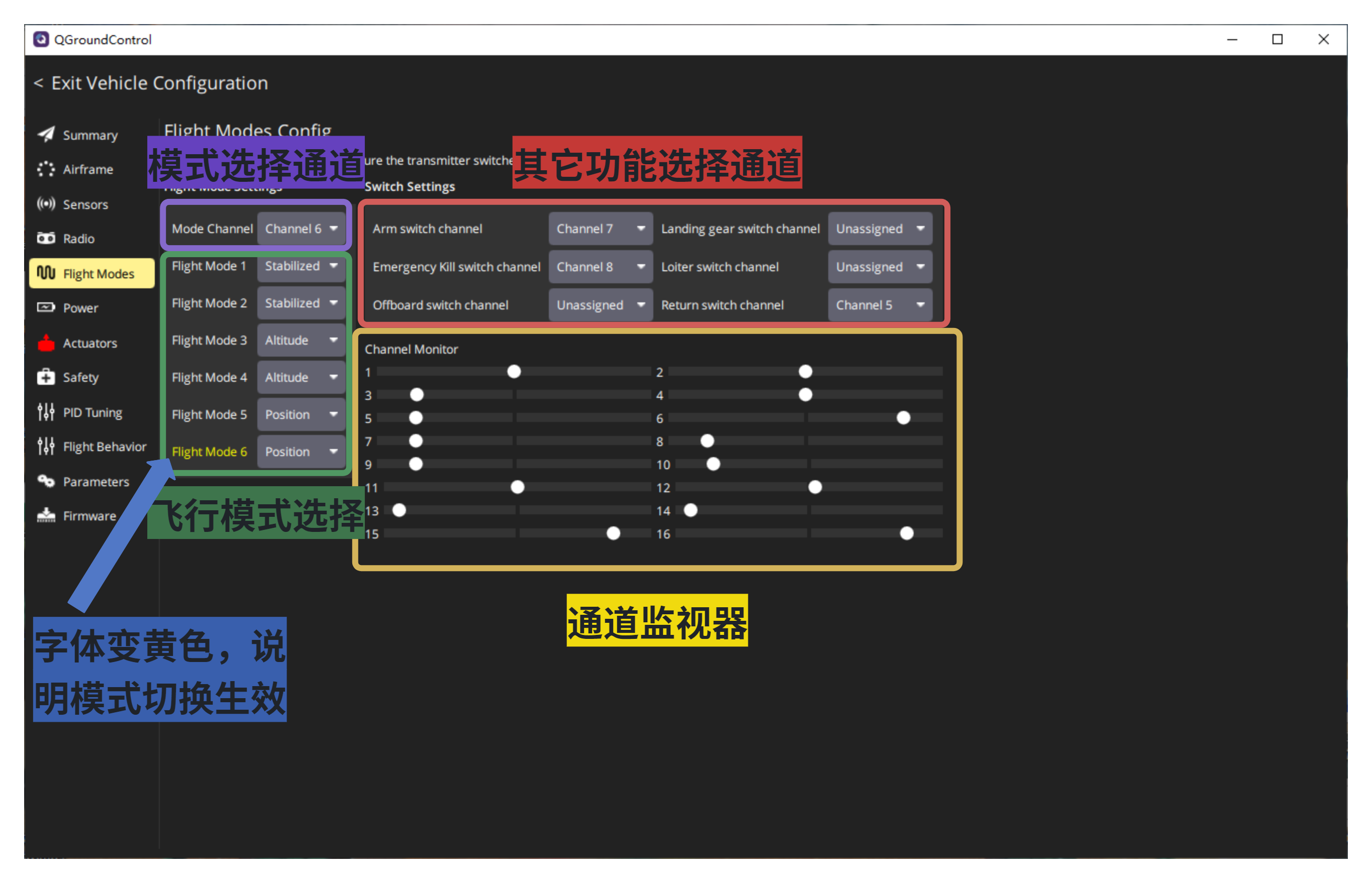
根据“Channel Monitor”通道监视器来确定遥控器上所有按键开关和拨杆对应的通道是哪个(一定要能对应上,否则会导致控制异常)。每次逐一按键或者拨杆,哪个数字上的点有变动就是对应哪个通道。
“Mode Channel”:用于选择通道来切换飞行模式(一般选择3档的拨码开关)。
“Flight Mode”:用于指定飞行模式,一般选用“Stabilizeb”自稳姿态飞行模式(完全手动控制)、“Altitude”高度飞行模式(飞行高度不变,水平控制)和“Position”定点飞行模式(在有GPS情况下飞行位置完全不变)。
其它功能选择通道用于一键实现某个功能。
“Arm switch channel”:报警切换通道。用于解锁飞机,电机这时会转动起来,加大油门即可起飞。
“Emergency Kill switch channel”:紧急闭锁切换通道。用于立马停止电机转动,无论飞机在哪里或者怎样飞行中(非紧急情况,千万不要随意触发该功能,否则会造成严重后果)。
“Offboard switch channel”:离线切换通道。在接有机载计算机情况下,飞控不再控制飞行,改为由机载计算机控制。
“Landing gear switch channel”:降落架切换通道。用于固定翼强制收起或者下放降落架。
“Loiter switch channel”:定点悬停切换通道。让飞机立马切换到定点悬停飞行(要有GPS)。
“Return switch channel”:返航切换通道。让飞机立马开始返航(要有GPS)。
3.3 、飞机状态查看(一定要插TF卡)
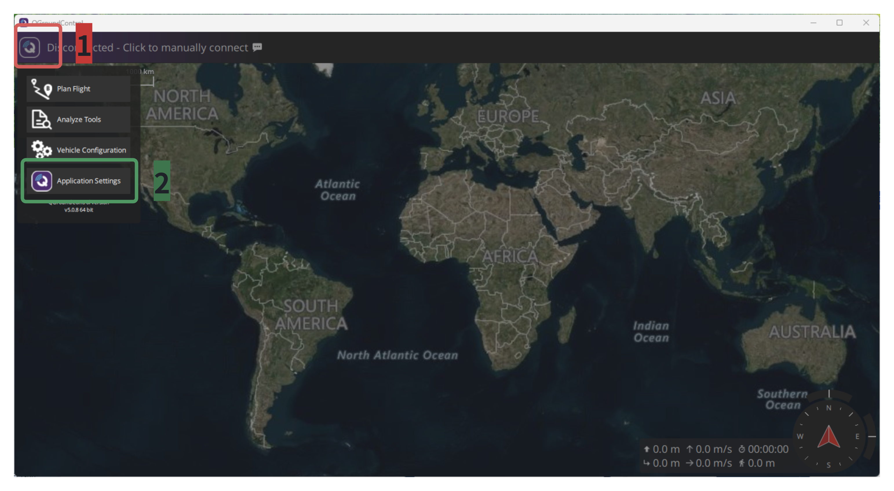
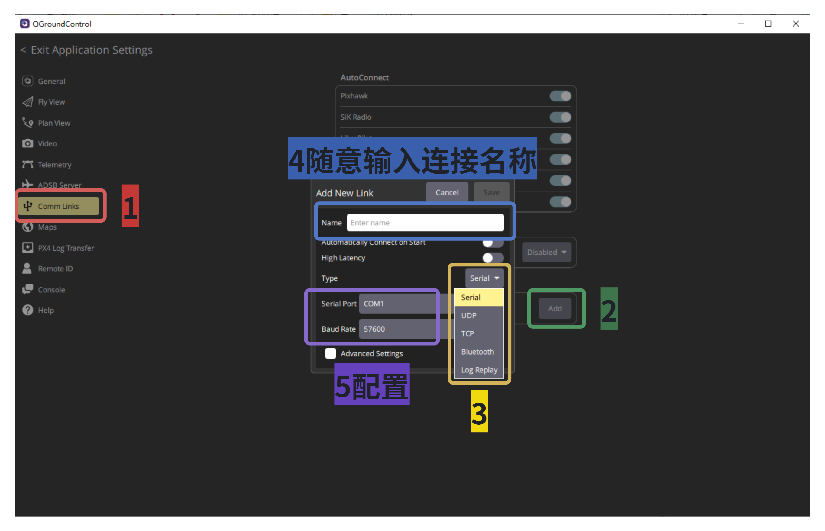
- 飞控有多种方式可以连接电脑与QGC软件进行通讯来查看飞机状态以及系统调试。通过点击左上角QGC图标进入“Application Settings”,选择"Comm Links"来进行添加连接方式。
通过USB直接连接飞控和电脑(默认使用的方法,无需额外模块无需配置)。
通过数传无线连接电脑和飞控(最方便最远距离,需要有一对数传)。选择“Serial”串口类型,“Serial Port”串口接口选择电脑识别到的数传端口号,“Baud Rate”串口波特率根据数传的规格来选择。
通过以太网连接电脑和飞控(最常用与机载计算机搭配,需要飞控支持以太网)。飞控和电脑要处于同一段网络下才能连通。
通过蓝牙无线连接电脑和飞控(最方便短距离,需要飞控和电脑都支持蓝牙)。选择“Bluetooth”蓝牙类型,点击“Scan”扫描蓝牙,连接对频后连接上即可。
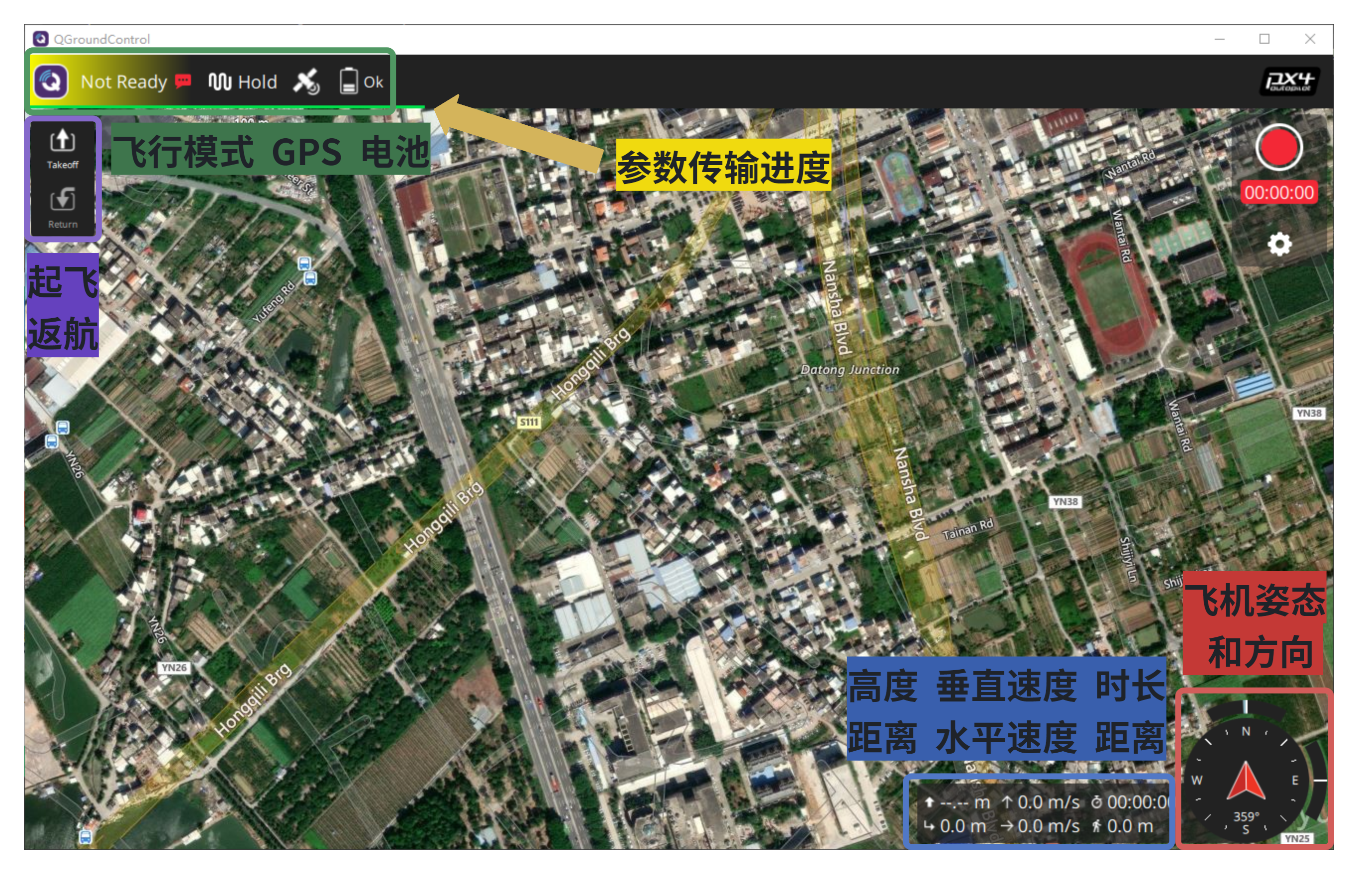
- 通过QGC软件的初始菜单,能够看到飞机的基本状态信息。当飞机开始连接QGC软件时,会有一个进度条显示飞控传输给QGC软件参数信息进度,只有当进度条消失后才能进行调试配置和起飞。
飞机的姿态(IMU)和方向(磁罗盘)。
飞机的速度,距离,高度和连通QGC的时长。
飞行模式、GPS信号和电池状态(飞行模式显示绿色代表飞机可以解锁起飞,显示黄色或者红色代表飞控还没配置完成或者不满足该飞行模式,此时需要检查飞控报错原因)。
还一键起飞和一键返航操作。
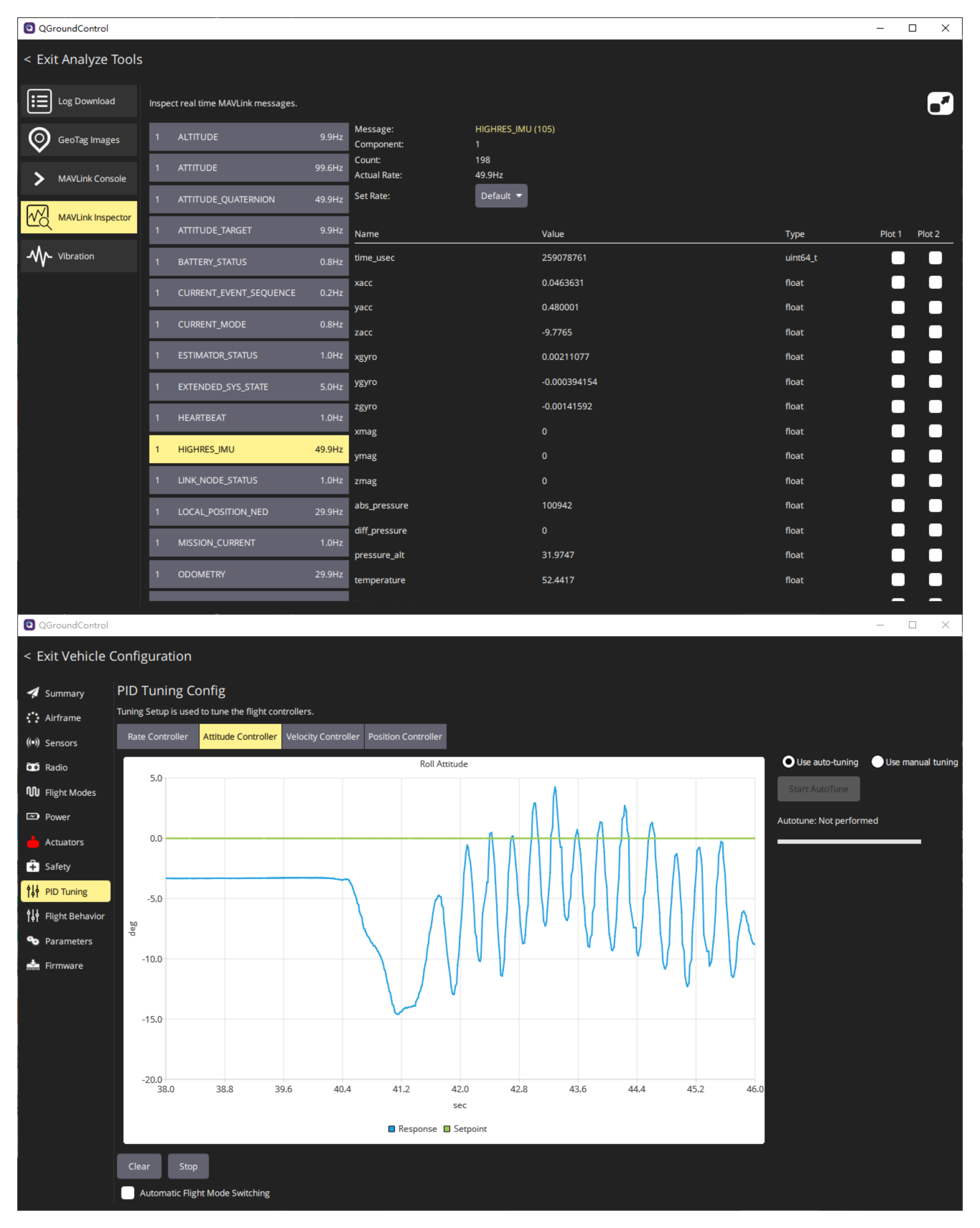
- 通过参数化实时看飞机的状态。通过点击左上角QGC图标进入“Analyze Tools”,选择"MAVLink Inspector"来进行查看飞机所有状态的参数值是多少。或者通过点击左上角QGC图标进入“Vehicle Configuration”,选择"PID Tuning"来进行查看飞机各个传感器的实时图表状态。
3.4、日志查看
PX4可以通过日志查看来完全了解飞机飞行过程的所有状态,比用QGC查看更加直观和全面(但是无法实时,只能用于事后分析)。因此都需要从TF卡里面把飞行日志下载下来。
通过点击左上角QGC图标进入“Analyze Tools”,选择"Log Download"来进行下载飞行日志到电脑本地(无需读卡器,只要飞控和电脑连通即可)。或者直接通过读卡器,把飞行日志复制到电脑本地。
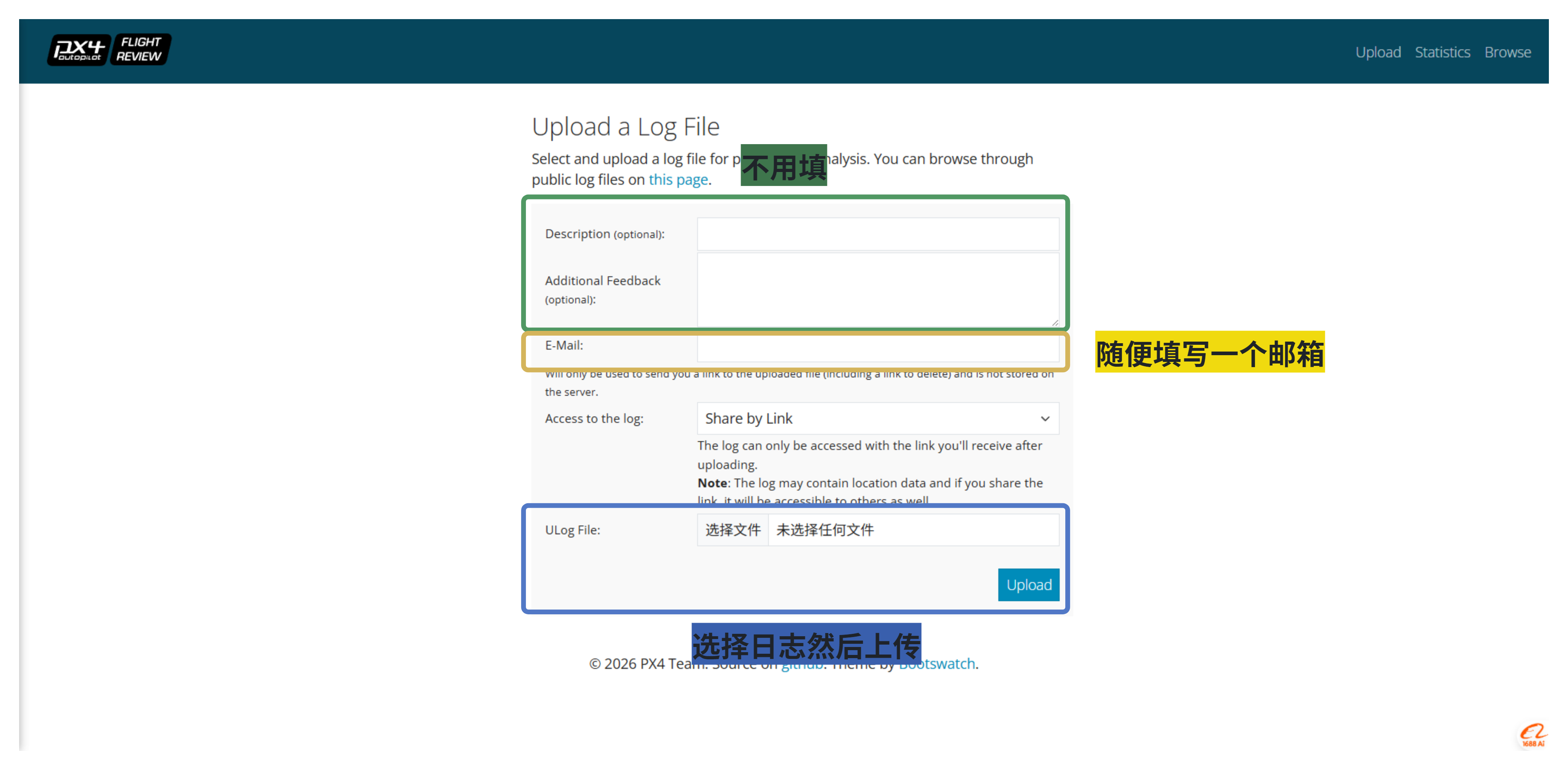
通过Flight Review网站https://logs.px4.io/(需要科学上网),上传日志后就会自动生成飞行轨迹、各个传感器参数和飞行状态等各种参数图表(看不懂可以问下豆包)。
- 其它工具如PlotJugler、pyulog、FlightPlot、PX4Tools、MAVGCL和Data Comets均支持在本地部署查看日志,按照自身使用习惯即可(均可在GitHub上下载安装包)。