1. Product Introduction
FY-ESC-DP-60A is a four-in-one brushless electronic speed controller (ESC) based on AM32 firmware, featuring high responsiveness, high power, high performance, and high protection. The ESC has two built-in high-power adjustable BEC output interfaces and multiple direct power connection output interfaces, which can provide power for onboard computers and lidars, eliminating the need for additional external power distribution boards and BEC boards to meet the power supply requirements of the entire drone system. Meanwhile, it uses ultra-large protection tubes and high-specification field-effect transistors, making it immune to the impact of back electromotive force caused by sudden stops.
2. Product Specifications
2.1 Basic Specifications
| Specification | Parameter |
|---|---|
| Size | 50x50x8mm |
| Positioning hole | 30.5x30.5mm-M4x4 |
| Weight | 24g |
| Operating Temperature | -40~85℃ |
| Connector | **BEC: Type-C + 2P SH1.0mm Connector + Solder Joint ** |
| **Power Supply: Pin Header + 4P SH1.0mm Connector + Solder Joint ** | |
| Control port: 8P SH1.0mm connector | |
| Motor: Solder Joint |
2.2 Electrical Specifications
| Specification | Parameter |
|---|---|
| Input Voltage | 3~6S(9~26V) |
| Single-channel electric adjustment | **Rated: 60A ** |
| **Instantaneous: 65A (10s) ** | |
| Single-channel BEC | **Switchable output 5/12V - 5A ** |
| **Voltage Detection ** | ±1.5% accuracy, detection: actual -1: 9.06 |
| **Current Detection ** | ±2% accuracy, detection: actual -1:100.2 |
| Supported Protocols | Dshot300/Dshot600/Bidirectional Dshot/PWM |
3. Interface and Connection Instructions
3.1 Three-phase Brushless Motor Connection
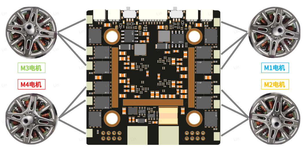
Supports welding motor wires on both the front and back sides, with extra-large pads for easy soldering. There is no specific wire sequence for motor soldering; simply solder the three phases correspondingly. 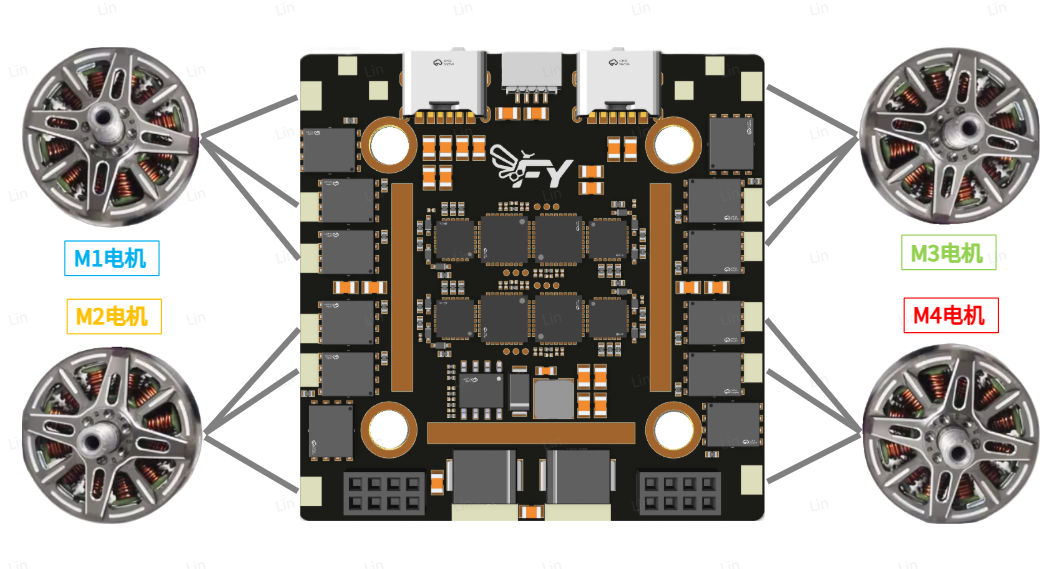
3.2 Power Input/Output Interface
Since the power input requires a large current, it is necessary to connect at least an externally connected cable of 12 AWG or larger. At the same time, only the large solder joint can be used as the input terminal, and other interfaces should be used as output terminals; otherwise, insufficient overcurrent may cause burnout. 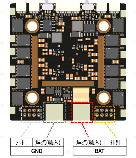 The direct power connection output interface is used for externally expanding the BEC board or distributing power to other modules. Among them, the pin headers can be soldered on both sides for use, facilitating the power supply of other expansion boards when stacked, greatly facilitating extended applications.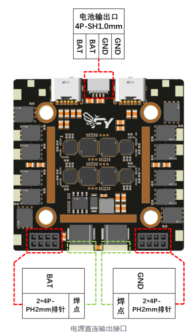
BAT: Positive Terminal of Power Supply
GND: Negative Power Supply
3.3BEC Switch and Output Interface
| Indicator Light | Status |
|---|---|
| Red light on, blue light off | BEC Output 12V |
| The red light goes out and the blue light comes on | BEC Output 5V |
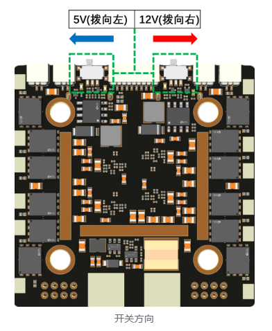
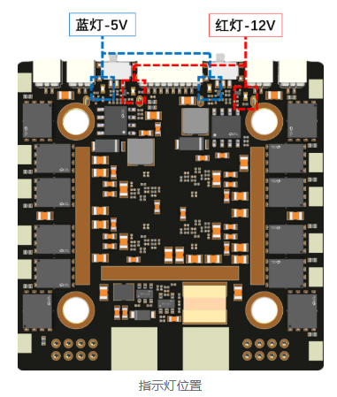 The same BEC can only switch to 5V or 12V output at the same time, without any other voltage value output. When the switch is turned to the left, it outputs 5V; when turned to the right, it outputs 12V. The two BECs are independently controlled and output, without being affected by each other.
  Multiple connectors on the same BEC can output simultaneously, but the total current output from all interfaces of the same BEC cannot exceed 5A; otherwise, it may cause abnormal output or even burn out the BEC. When outputting 12V, an input power supply (battery) greater than 12V must be connected; otherwise, it will cause abnormal output voltage. The voltage output by the connector is controlled by the nearest switch.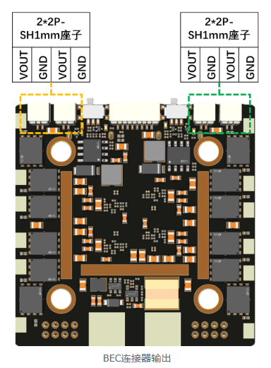
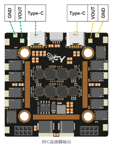
VOUT: BEC Output Positive Terminal
GND: Negative pole of BEC output
3.4 Control Interface
It is used to connect a controller (such as a flight controller) for communication and control of the electronic speed controller, and can output the corresponding voltage value converted from the detected input power supply voltage and current, as well as provide power to the controller.
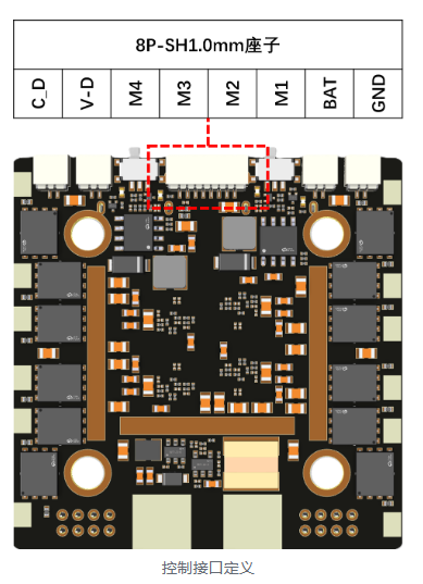
C-D: Voltage value converted from the power supply current detected by the ESC
V-D: Voltage value converted from the power supply voltage detected by the ESC
M4~M1: ESC control input signal
BAT: Positive Output of Power Supply
GND: Negative Power Supply
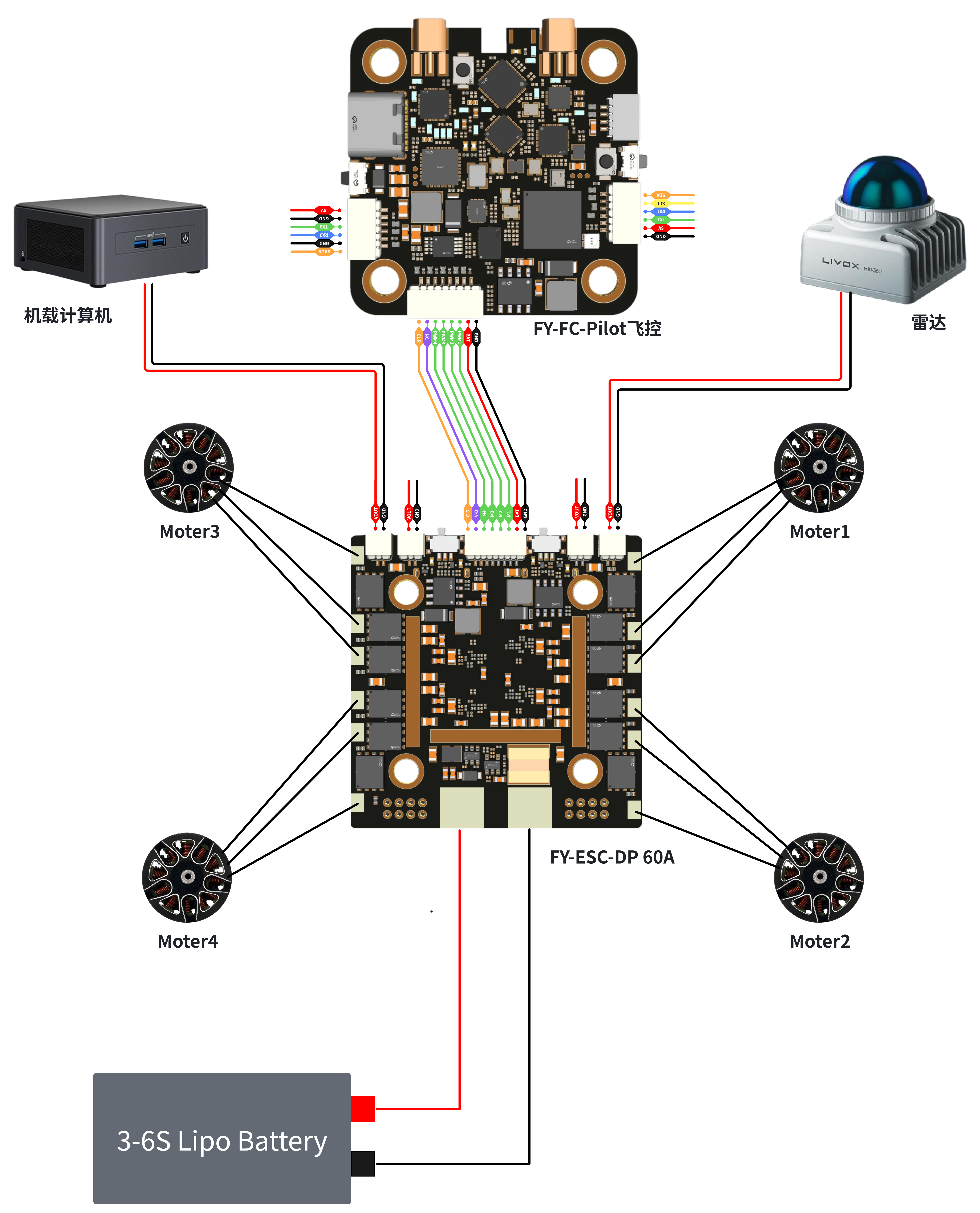
3.5 Reference Application Scenarios
4. Product Accessories List
| Product Accessories | Quantity |
|---|---|
| FY-ESC-01 Module | 1 |
| 470uF/35V High Frequency Low Resistance Capacitor | 1 |
| M3*8 Shock Absorbing Column | 4 |
| 8P-SH1.0mm-10cm Co-directional Connector Wire | 1 |
| 12awg wire with XT60 connector | 1 |
5. Precautions
The product is strictly prohibited from being used in any local war. If the purchaser privately uses it in war and all liabilities arising therefrom shall have nothing to do with the supplier.
If the product is damaged due to non-quality issues, the supplier will not provide warranty.
When receiving the product, the purchaser should conduct an unpacking test as soon as possible according to the instructions, ensure that there are no issues before installing and using it, and avoid scratching the module, which may result in the inability to return or exchange it.
When problems occur during use, the problem site should be photographed and recorded as much as possible, and the supplier should be promptly informed for handling.