1. Product Introduction
FY-FC-Pilot is a highly integrated and multi-functional flight controller specifically designed for unmanned system scenarios. It deeply integrates key functional modules such as remote control reception and data transmission into one, effectively simplifying the complexity of hardware connections in unmanned devices and enhancing system integration efficiency and operational stability. It is equipped with a 32-bit high-performance STM32H743 processor, which has powerful data processing capabilities and can simultaneously run multi-task programs such as attitude calculation, path planning, and power control. Meanwhile, the flight controller integrates multiple protection functions, making it immune to the impact of back electromotive force caused by sudden ESC stops.
2. Product Specifications
1. Basic Architecture
| Hardware | Parameter |
|---|---|
| Master Control | STM32H743 (main frequency 480MHz) |
| **Accelerometer and gyroscope ** | BMI088 |
| barometer | SPA06-003 |
| Remote Control Reception | ELRS remote controller compatible with 2.4GHz frequency band |
| Data Transmission | Used in conjunction with FY-DT-3000 |
2. Interface Types
| Interface Type | Quantity |
|---|---|
| PWM Output | 4+4 (SH1.0mm connector) |
| SBUS Input | 1 (SH1.0mm connector) |
| I2C Interface | 1 (SH1.0mm connector) |
| UART Interface | 3 (SH1.0mm connector) |
| TF Card Interface | 1 (TF Card Connector) |
| USB interface | 1(Type-C) |
| Power Interface | 2 (SH1.0mm connector) |
| Antenna Interface | 2 (MMCX Antenna Port) |
| Pairing button | 2 (data transmission + remote control) |
| ADC Input | 2(Current + Voltage) |
| **Burn Button ** | 2 (Flight Control + Remote Control) |
3. Regular Specifications
| Specification | Parameter |
|---|---|
| Size | 40x40x8mm |
| Positioning hole | 30.5x30.5mm - 4xM4 |
| Weight | 13g |
| Power Input | 3-6s(9-27V) |
| BEC Output | 5V(5A)+7.7V(2A) |
| **Firmware ** | PX4-V1.16.1 |
| Supported Models | Multirotor/Fixed-wing/Helicopter/Unmanned Surface Vehicle/Unmanned Ground Vehicle, etc. |
| Pin Level | **All functional pins for input and output have a voltage level of 3.3V ** |
| **Voltage Detection Ratio ** | 11:1(11) |
3. Connection Instructions
1. Antenna Connection
The remote control receiver end uses a 2.4GHz T-shaped antenna with MMCX male inner pin by default. The data transmission end uses a 915MHz T-shaped antenna with MMCX male inner pin by default. (Note: Antennas need to be used in pairs to achieve normal performance, i.e., T-shaped antennas should be paired with T-shaped antennas or rubber rod antennas should be paired with rubber rod antennas.) 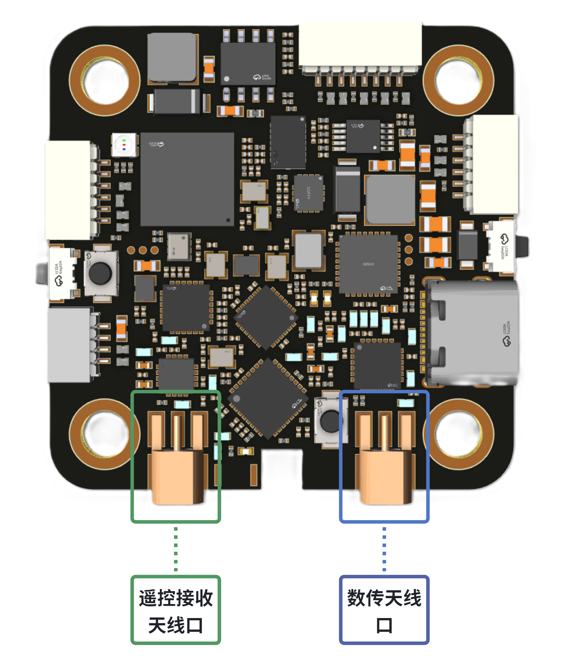
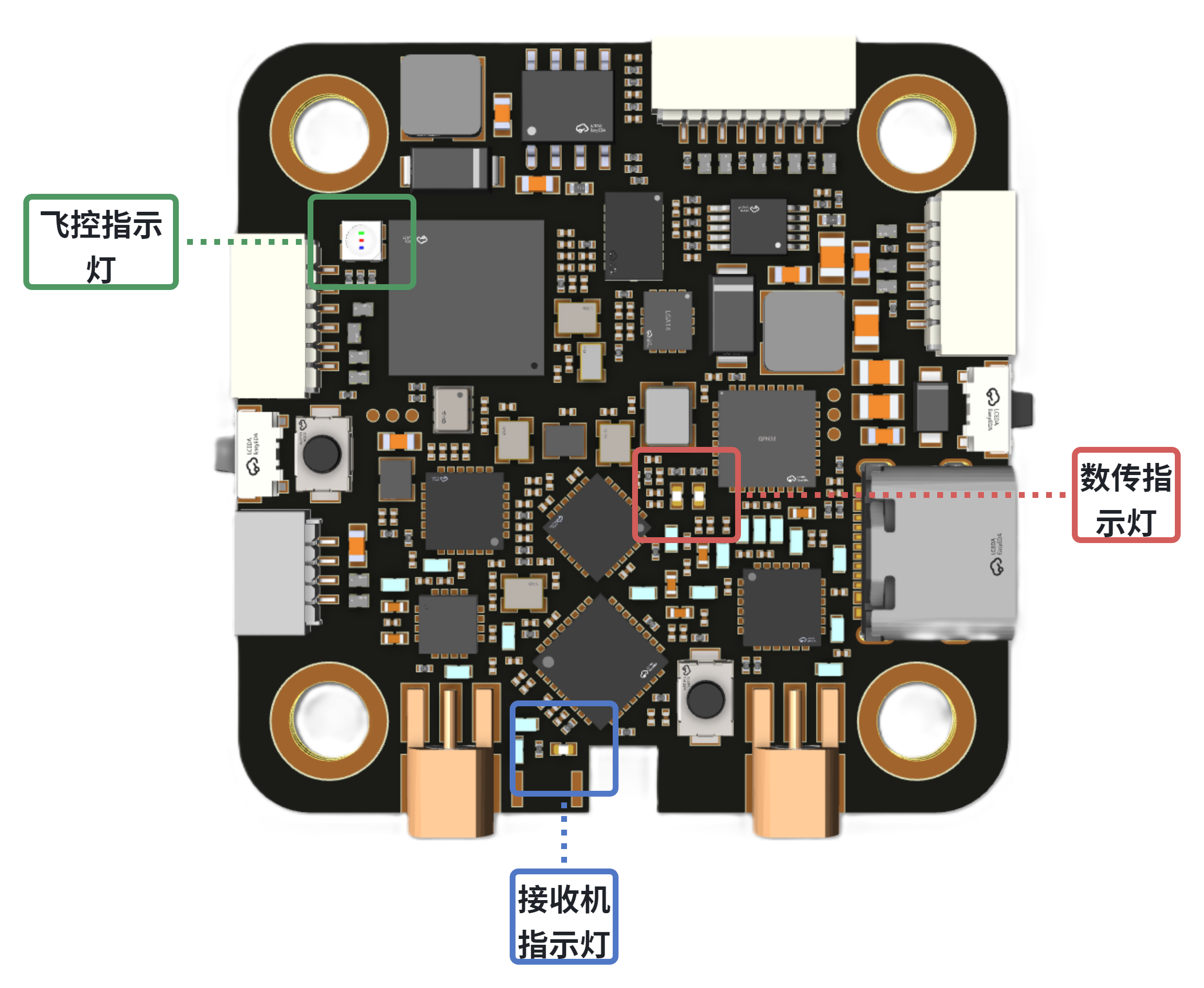
2. Status Indicator
- Remote control receiver (blue light):
| Chang Liang | **Frequency pairing with the remote control was successful ** |
|---|---|
| Slow Blinking | Waiting to pair with the remote control |
| Fast blinking | **Without remote control frequency pairing, enter the wireless upgrade mode of the receiver ** |
- Data Transmission Terminal (Blue Light + Red Light):
| Blue light on constantly + Red light off | **has been frequency paired with another data transmission module ** |
|---|---|
| Blue light not lit + Red light flashing | **Frequency pairing of countless transmission modules ** |
| **The blue light and red light flash alternately ** | Waiting to pair frequencies with another data transmission module |
- Flight control terminal (red light + blue light + green light):
| **Only the green light is flashing ** | **Only the bootloader file was burned ** |
|---|---|
| Only the blue light is flashing | **Flight control system starts normally ** |
| Only the red light is flashing | **Flight control anomaly ** |
3. Frequency pairing operation
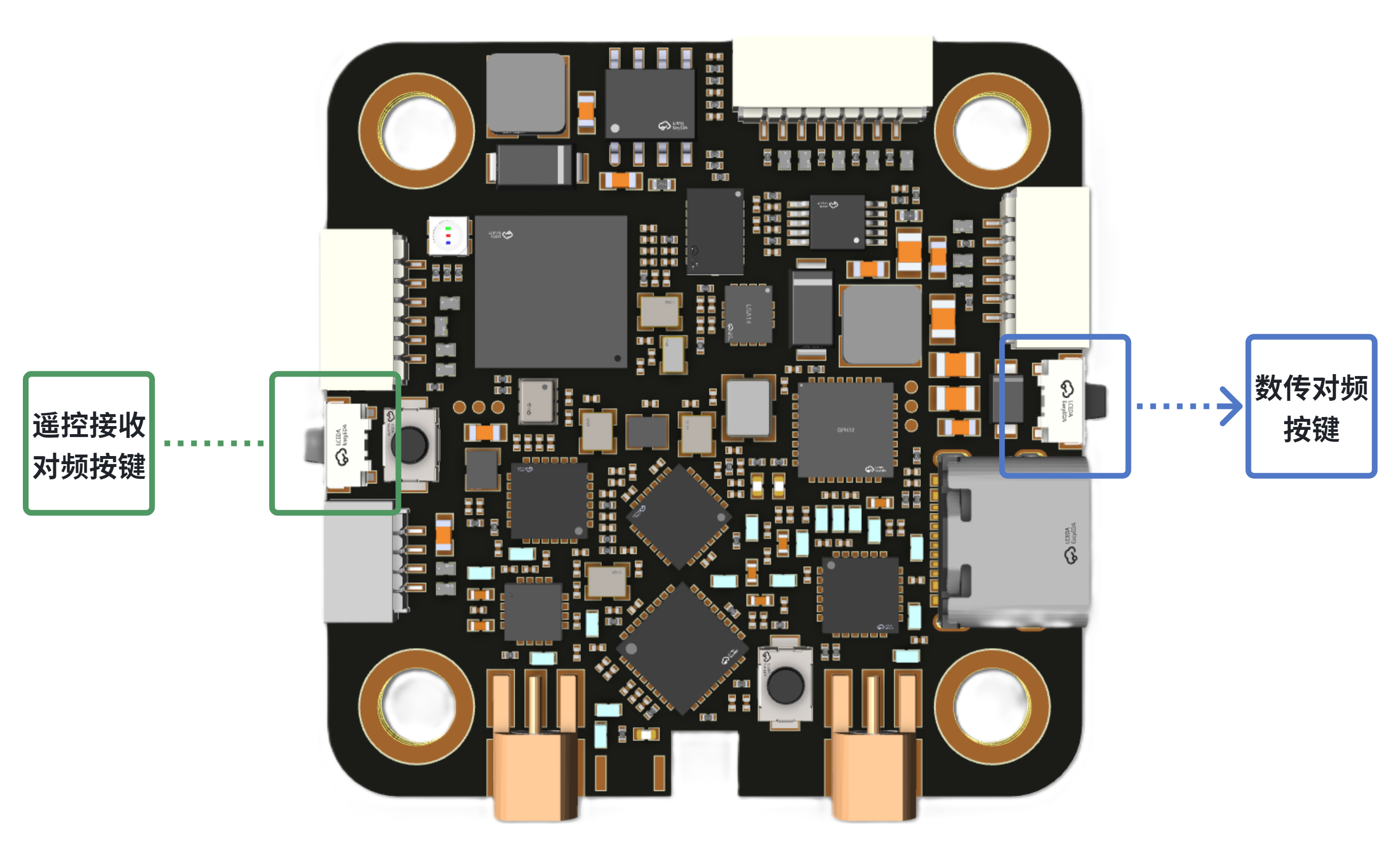
Remote control receiver: Turn on the remote control and enter the frequency pairing mode, then quickly press the frequency pairing button on the flight control module 3 times. Wait until the indicator light flashes slowly.
Data Transmission End: Simultaneously press and hold the frequency pairing button on the flight controller and the frequency pairing button on another data transmission module for more than 3 seconds until the red and blue indicator lights flash alternately.
4. Power Interface
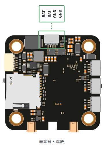
The flight controller has two power input ports, both of which can be used to power the flight control system. It also integrates a current detection interface. The power interface has a reverse polarity protection function (the functional pins do not have this function, so please carefully check the wiring before powering on to avoid burning out the module). 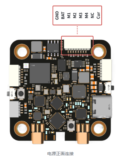
5. ESC Connection
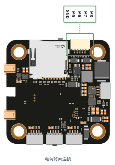
Supports up to 8-channel ESC control outputs, supporting protocols such as PWM and Dshot (Dshot300 output is recommended). 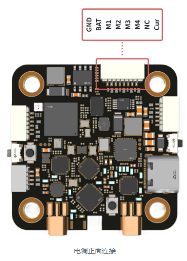
6. Serial Port Connection
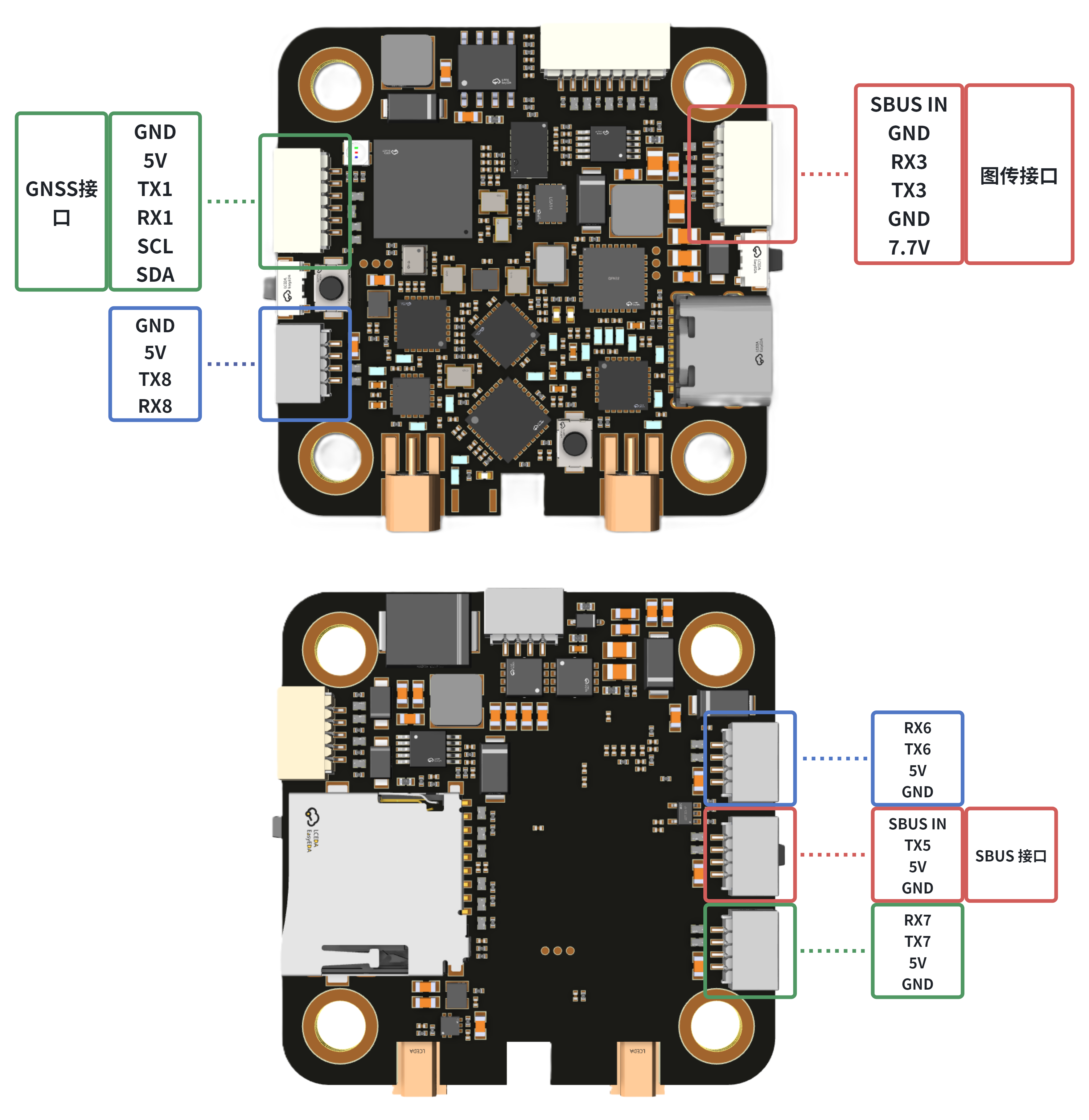
When the flight control serial port is connected to an external module, it needs to be connected in a cross-connection manner with TX connected to RX. Serial port mapping relationship:
| PX4 | |
|---|---|
| UART1 | GPS1 |
| UART2 | TELEM1 (already used as a remote control receiver) |
| UART3 | GPS2 |
| UART4 | TELEM2 (already used for data transmission) |
| UART5 | Radio controller (only supports SBUS) |
| UART6 | Debug Interface, Terminal Communication |
| UART7 | TELEM3 |
| UART8 | TELEM4 |
7. Other Interfaces
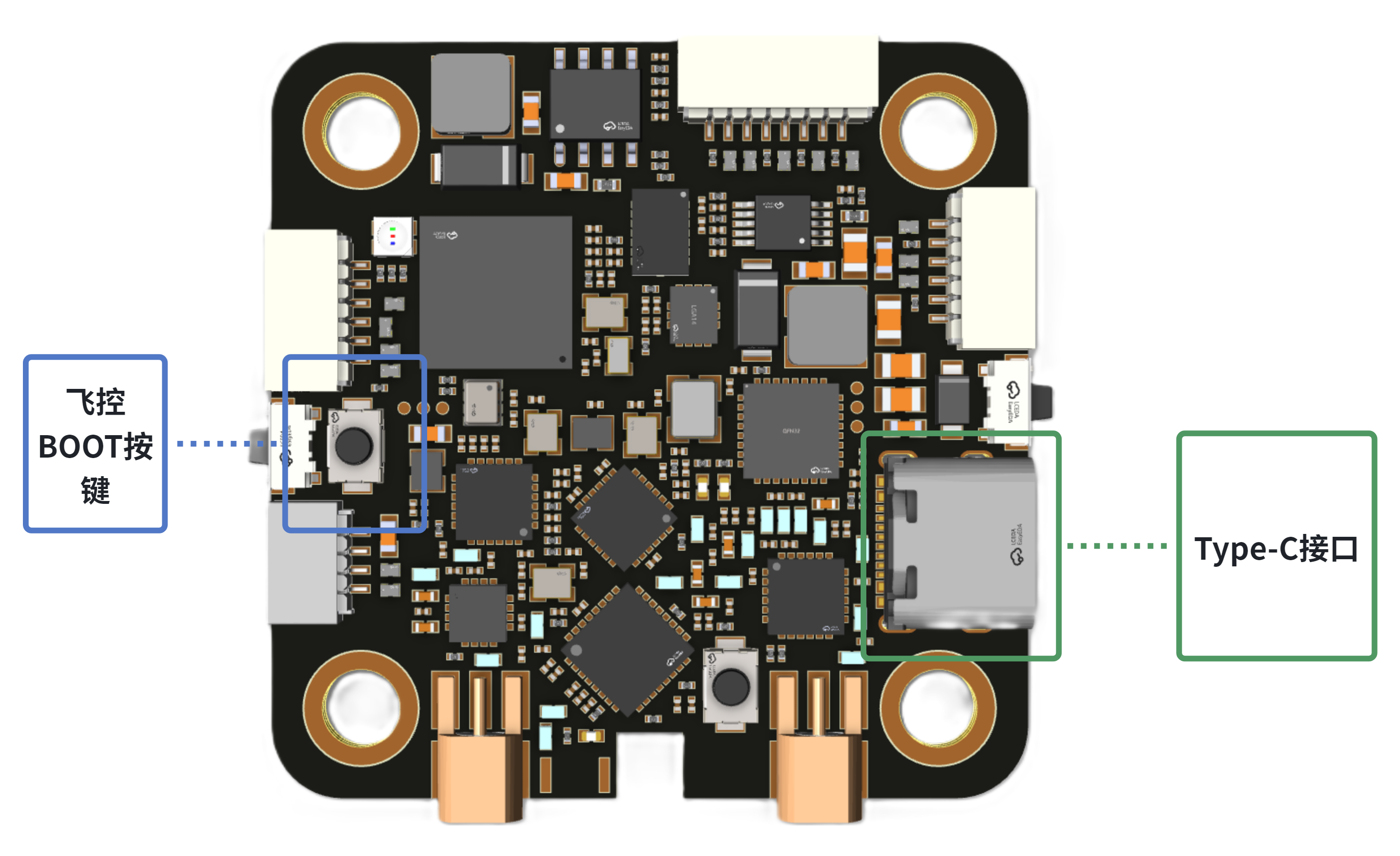
- The flight controller burns the program through the Type-C interface. You can press and hold the BOOT button to power on the computer via Type-C connection, then release the button to burn the program. After the burning is completed, you can use the Type-C interface to debug the flight controller.
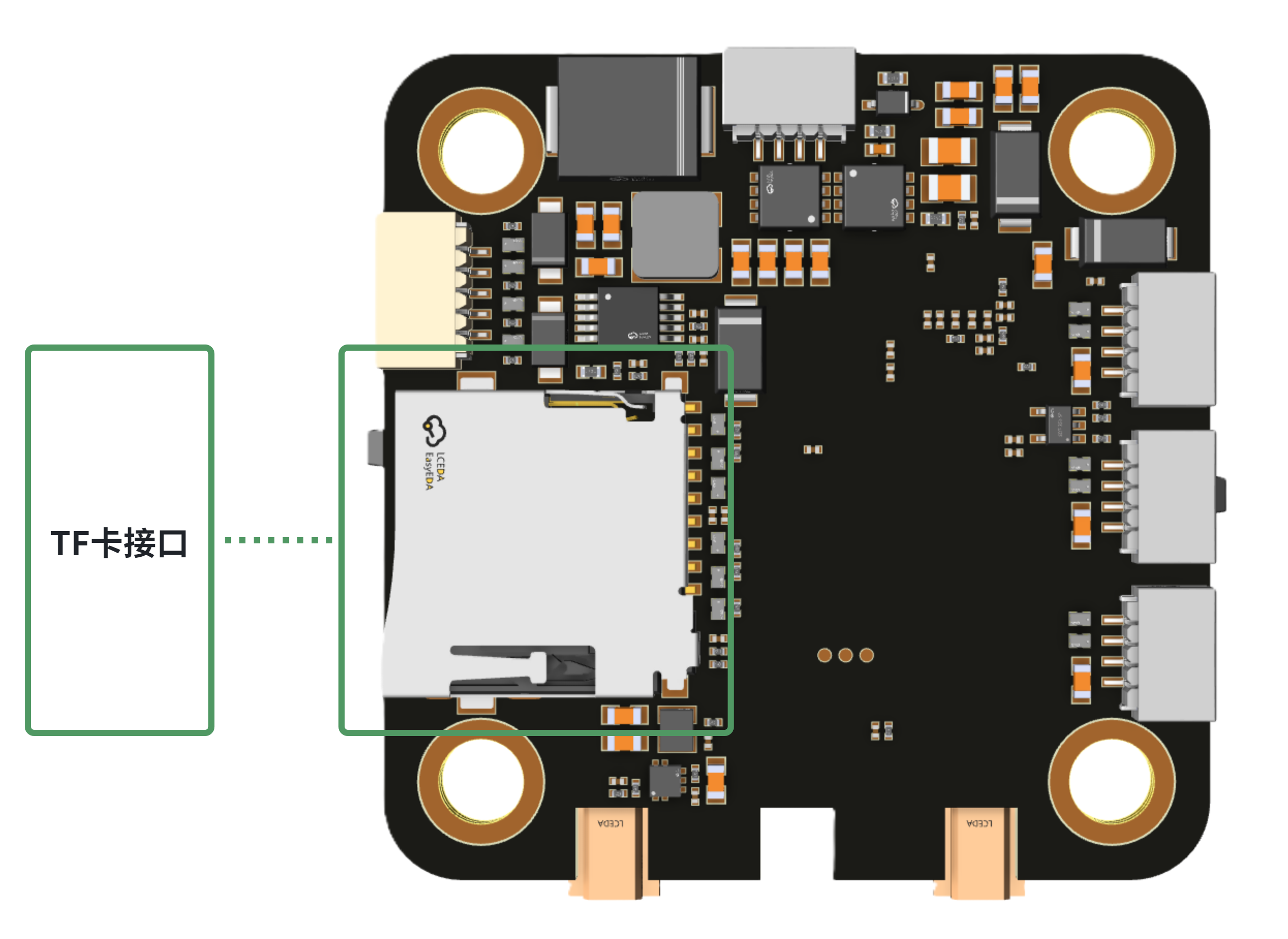
- TF Card Interface: It is recommended to use a TF card from a well-known brand for operations such as logging.
8. Nose Orientation
By default, the antenna outlet is at the rear of the unit, and the side with the indicator light facing up is the front. 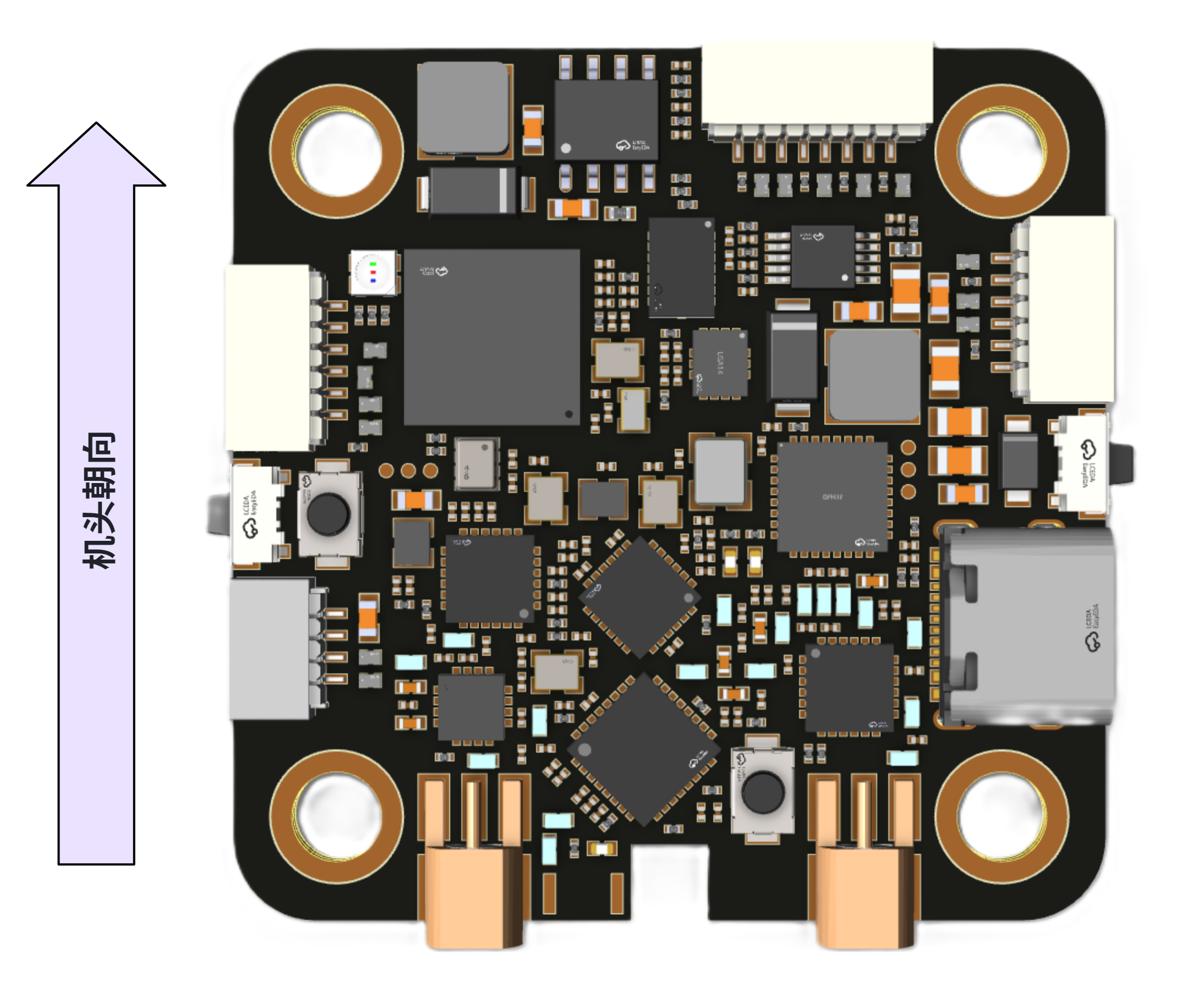
4. Shipping Accessories List
| **Shipped Goods ** | Quantity |
|---|---|
| FY-FC-Pilot | 1 |
| FY-DT-3000 | 1 |
| M3X8 Shock Absorber Column | 4 |
| 8P-SH1.0mm-10cm Co-directional Plug Wire | 1 |
| 6P-SH1.0mm-10cm Co-directional Plug Wire | 1 |
| 6P-SH1.0mm-20cm Co-directional Plug Wire | 1 |
| 4P-SH1.0mm-10cm Co-directional Plug Wire | 5 |
| 5P-SH1.0mm-10cm Co-directional Plug Wire | 1 |
| 2.4G T-shaped antenna with MMCX elbow | 1 |
| 915M T-Type Antenna with MMCX Elbow | 1 |
5. Precautions
The product is strictly prohibited from being used in any local war. If the purchaser privately uses it in war and all liabilities arising therefrom shall have nothing to do with the supplier.
If the product is damaged due to non-quality issues, the supplier will not provide warranty.
When receiving the product, the purchaser should conduct an unpacking test as soon as possible according to the instructions, ensure that there are no issues before installing and using it, and avoid scratching the module, which may result in the inability to return or exchange it.
When problems occur during use, the problem site should be photographed and recorded as much as possible, and the supplier should be promptly informed for handling.